| SVC(TND) | 0.5 | kVA |
| Product model | Rated capacity | Capacity unit |
| SVC(TND):single-phase AC voltage regulator SVC(TNS):three-phase AC voltage stabilizer |
0.5、1 ... 100kVA |
kVA |
The stabilized voltage power supply has the characteristics of beautiful appearance, low selfloss,complete protection functions, etc.It can be widely used in production,scientific research, medical and health care, air conditioners, refrigerators and other household appliances.It is an AC stabilized voltage power supply with ideal performance and price.
● Ambient temperature:-5~+40 °C;
● Relative humidity: no more than 90% (at 25 °C);
● Altitude: ≤ 2000m;
● Working environment: indoor without chemical deposit, dirt, harmful corrosive medium and flammable and explosive gas;it can work continuously.
See Table 1 for main technical indicators
| Project/Number of phases (Table 1) | Single-phase | Three-phase |
| Input voltage range | 160~250V | 280~430V |
| output voltage | 220V±25% | 380±3% |
| Overvoltage protection value | 246±4V | 246±7V |
| Voltage regulating speed | <1s(when the input voltage changes 7.5V) | |
| Rated frequency | 50Hz | |
| Electrical strength | Withstand 50Hz sine AC 1500V in cold state for 1min | |
| Load power factor | 0.8 | |
| Efficiency | More than 90% | |
Note:
1. The technical indicators of each unit refer to those shown on the enclosure.Single phase 0.5-3kVA with 110V±3% output voltage;
2. The in put voltage exceeds the above range, and special technical indicators can be specially ordered.

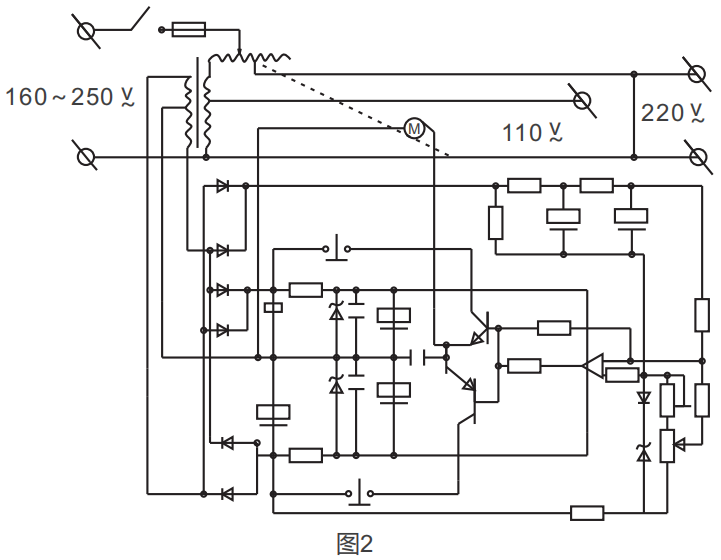
● The electrical schematic diagram of 0.5kVA~1.5kVA high-precision full-automatic AC voltage stabilizer is shown in Figure2;
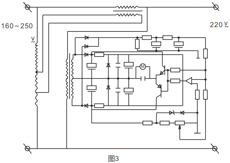
● See Figure3 for electrical schematic diagram above SVC-5kVA;
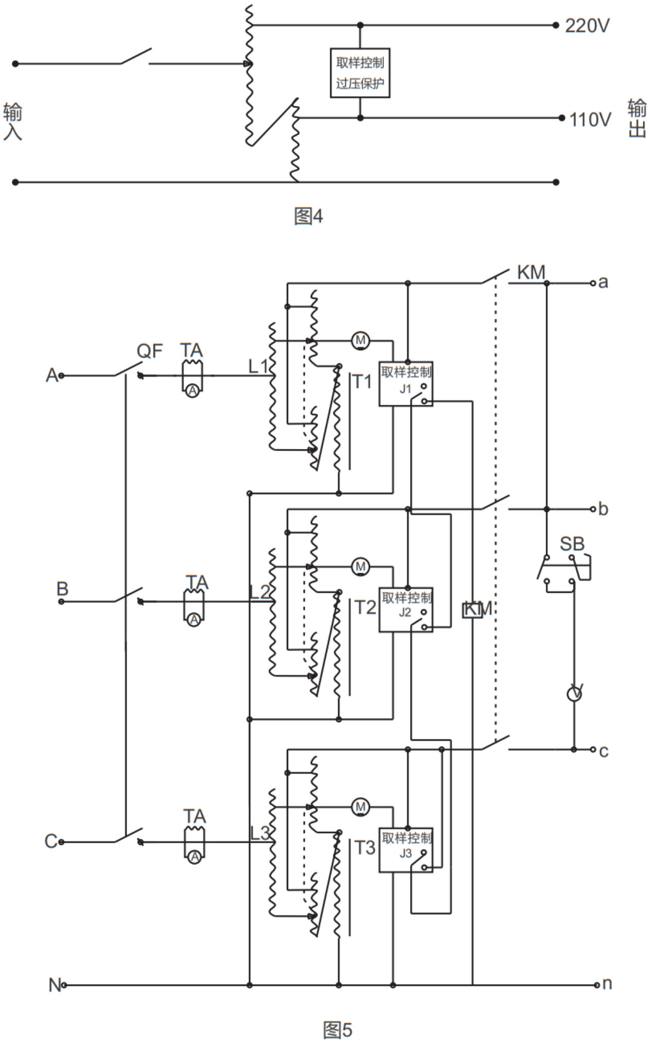
● See Figure4 for the electrical schematic diagram of single-phase voltage regulator;
● The electrical schematic diagram of three-phase voltage regulator is shown in Figure5.


SVC-0.5kVA~1.5kVA high-precision full-automatic AC voltage regulator:

SVC-2kVA~3kVA high-precision full-automatic AC voltage regulator:

1. Voltmeter
2. Voltage measurement button
3.Overvoltage indicator (red)
4. Working indicator (green)
5.Undervoltage indicator (yellow)
6.Power switch

7.Grounding
8.Input phase line
9.Input zero line
10.Output phase line(110V)
11.Output zero line(110V)
12.Output phase line(220V)
13.Output zero line(220V)
Note: For the wiring mode, single-phase SVC-2kVA~5kVA, unscrew the wiring screws fixed at the back of the backplane, use the section area of the bare wire part of the conductor to meet the needs of conducting current during load, press the stripped bare wire part at the top of the conductor fully according to the wiring diagram, and tighten it. It is strictly prohibited to loosen the screws in the front row of the wiring board to fix the internal conductors and use the conductors that do not meet the actual capacity.

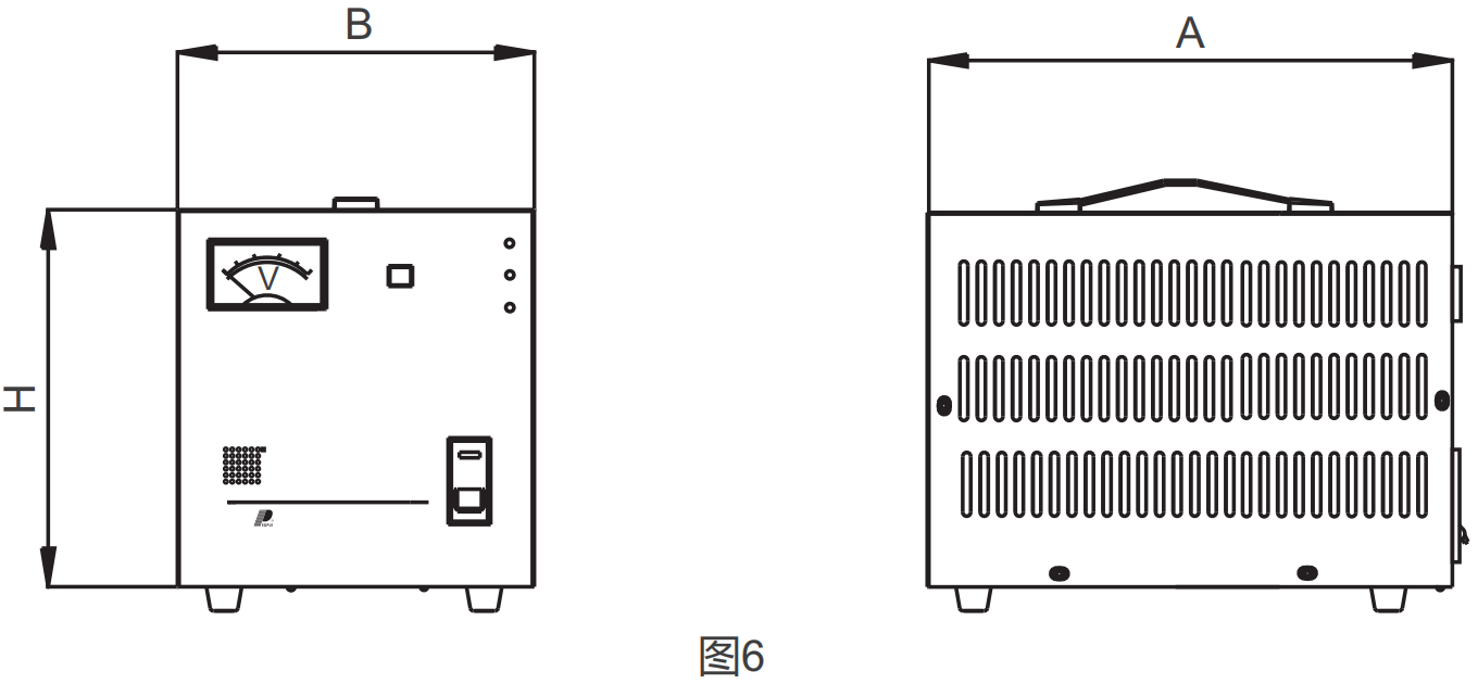
| Model(Table 3) | Capacity | Overall dimension AxBxH (cm) |
| SVC(single-phase) | 0.5kVA | 19×18×15 |
| 1kVA | 22×22×16 | |
| 1.5kVA | 22×22×16 | |
| 2kVA | 27×24×21 | |
| 3kVA | 24×30×23 | |
| 5kVA | 22×36×28 | |
| 7kVA | 25×41×36 | |
| 10kVA(Horizontal) | 25×41×36 | |
| 10kVA(Vertical) | 32×35×57 | |
| 15kVA | 35×39×66 | |
| 20kVA | 35×39×66 | |
| 30kVA | 50×50×96 | |
| SVC(three-phase) | 1.5kVA | 49×35×17 |
| 3kVA | 49×35×17 | |
| 4.5kVA | 49×35×17 | |
| 6kVA | 28×33×68 | |
| 9kVA | 33×33×76 | |
| 15kVA | 37×43×82 | |
| 20kVA | 37×43×82 | |
| 30kVA | 41×46×95 | |
| 50kVA | 56×60×130 | |
| 60kVA | 50×60×130 | |
| 100kVA | 66×50×129 |
The main technical indicators are shown in Table1
| Item/Phase | Single phase | Three phase | |||||||
| Input voltage range | 160~250V | 280-430V | |||||||
| The output voltage | 220V ± 2.5% | 380 ± 3% | |||||||
| Overvoltage protection value | 246 ± 4V | 426 ± 7V | |||||||
| Regulating speed | <1s (At an input voltage of 7.5V) | ||||||||
| rated frequency | 50Hz | ||||||||
| Electric strength | Withstand 50Hz sine AC 1500V in cold state for 1 min | ||||||||
| Load power factor | 0.8 | ||||||||
| Efficiency | >90% | ||||||||
Note:
1. technical specifications of each machine with reference to those shown on the housing, single-phase 0.5-3kVA with 110V±3% output voltage.
2. Input voltage beyond the above range, and special technical indicators can be customized by special order.
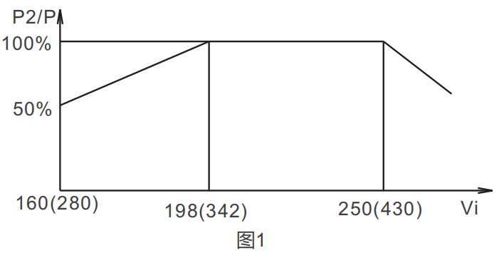
Output capacity curve, see Figure 1:
Figure (1) Output capacity curve
Vi input voltage
P2 output capacity
P rated output capacity
1. 0.5kVA-1.5kVA high precision fully automatic AC1 voltage regulator electrical schematic diagram in Figure 2.
2. the electrical schematic diagram of SVC-5kVA or above is shown in Figure 3.
3. single-phase voltage regulator electrical schematic diagram in Figure 4.
4. three-phase voltage regulator electrical schematic diagram in Figure 5
| Model No. | Capacity | Dimensions A x B x H (cm) | |||||||
| SVC (single phase) | 0.5kVA | 19 x 18 x 15 | |||||||
| 1kVA | 22 x 22 x 16 | ||||||||
| 1.5kVA | 22 x 22 x 16 | ||||||||
| 2kVA | 27 x 24 x 21 | ||||||||
| 3kVA | 24 x 30 x 23 | ||||||||
| 5kVA | 22 x 36 x 28 | ||||||||
| 7kVA | 25 x 41 x 36 | ||||||||
| 10kVA (horizontal) | 25 x 41 x 36 | ||||||||
| 10kVA (vertical) | 32 x 35 x 57 | ||||||||
| 15kVA | 35 x 39 x 66 | ||||||||
| 20kVA | 35 x 39 x 66 | ||||||||
| 30kVA | 50 x 50 x 96 | ||||||||
| SVC (three phase) | 1.5kVA | 49 x 35 x 17 | |||||||
| 3kVA | 49 x 35 x 17 | ||||||||
| 4.5kVA | 49 x 35 x 17 | ||||||||
| 6kVA | 28 x 33 x 68 | ||||||||
| 9kVA | 33 x 33 x 76 | ||||||||
| 15kVA | 37 x 43 x 82 | ||||||||
| 20kVA | 37 x 43 x 82 | ||||||||
| 30kVA | 41 x 46 x 95 | ||||||||
SVC-0.5kVA~1.5kVA Contact AC Voltage Stabilizer:
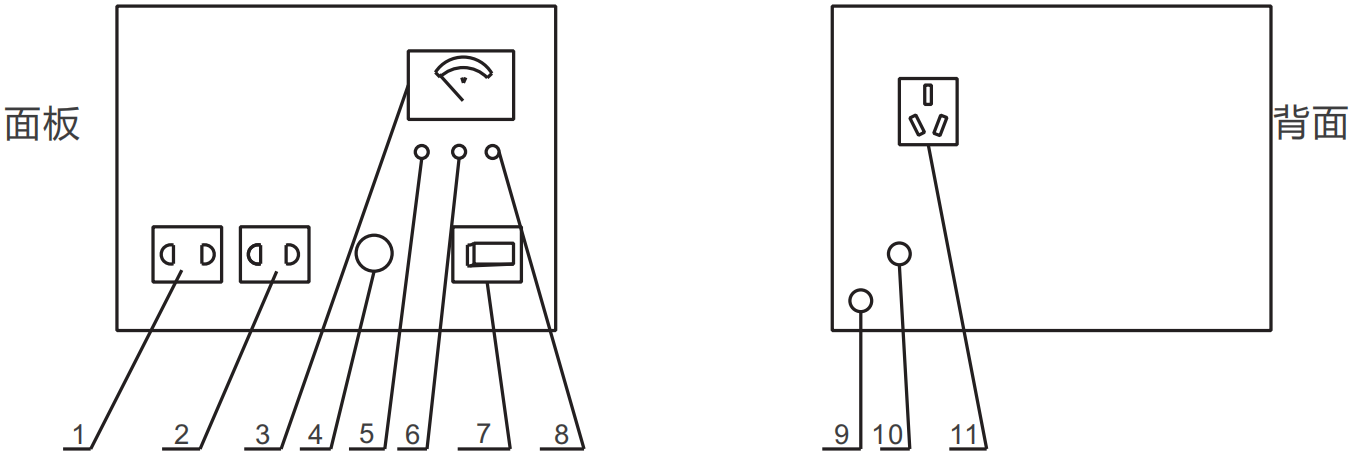
1. Two output sockets (220V)
2. Two output sockets (110V)
3. Voltmeter (output voltage)
4. Fuse holder (FU)
5. Working indicator light (green)
6. Undervoltage indicator light (yellow)
7. Power switch
8. Overvoltage indicator light (red)
9. Grounding
10. Input power cord
11. Output three sockets (220V)
SVC-2kVA~3kVA Contact AC Voltage Stabilizer:
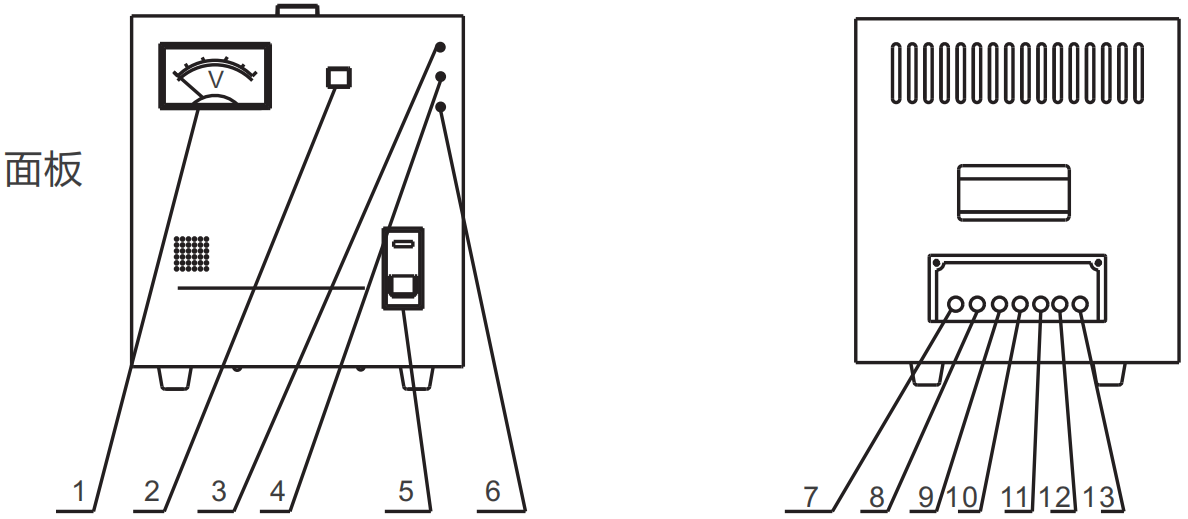
1. Voltmeter
2. Voltage measurement button
3. Overvoltage indicator light (red)
4. Working indicator light (green)
5. Power switch
6. Undervoltage indicator light (yellow)
7. Grounding
8. Input phase wire
9. Enter neutral line
10. Output phase wire (110V)
11. Output zero line (110V)
12. Output phase wire (220V)
13. Output zero line (220V)
Note: For the wiring method, single-phase SVC-2kVA~5kVA, you should unscrew the fixed wiring screws on the back of the bottom plate. The cross-sectional area of the wires meets the requirements of the maximum current under load. And fully, fasten it. It is strictly forbidden to loosen the screws fixing the internal wires in the front row of the terminal board and use wires that do not meet the actual capacity.
The product dimensions are shown in Figure 6.