
● Humidity: Relative humidity shall not exceed 50% at the Max temperature 40℃, and higher humidity could be accepted at lower temperature.The condensation must be taken care which is caused by temperature change.
● When temperature is above +40℃, location should be well-ventilated. When environment is unstandard, please using telecontrol or electrical cabinet,inverter working life is affected by install location.
● Longtime continuous using, the life electrolytic capacitor in inverter would not exceed 5 years, cooling fan life would not exceed 3 years, exchange and maintenance should be done earlier.
Voltage type: 380V and 220V
Applicative motor capacity:0.75kw to 355kw
| Voltage | Model No. | Rated capacity (KVA) | Rated output current (A) | Adaptive Motor (KW) |
| 380V three phase | RDI67-0.75G-A3 | 1.5 | 2.3 | 0.75 |
| RDI67-1.5G-A3 | 3.7 | 3.7 | 1.5 | |
| RDI67-2.2G-A3 | 4.7 | 5 | 2.2 | |
| RDI67-4G-A3 | 6.1 | 8.5 | 4 | |
| RDI67-5.5G/7.5P-A3 | 11 | 13 | 5 | |
| RDI67-7.5G/11P-A3 | 14 | 17 | 7.5 | |
| RDI67-11G/15P-A3 | 21 | 25 | 11 | |
| RDI67-15G/18.5P-A3 | 26 | 33 | 15 | |
| RDI67-18.5G/22P-A3 | 31 | 39 | 18.5 | |
| RDI67-22G/30P-A3 | 37 | 45 | 22 | |
| RDI67-30G/37P-A3 | 50 | 60 | 30 | |
| RDI67-37G/45P-A3 | 61 | 75 | 37 | |
| RDI67-45G/55P-A3 | 73 | 90 | 45 | |
| RDI67-55G/75P-A3 | 98 | 110 | 55 | |
| RDI67-75G/90P-A3 | 130 | 150 | 75 | |
| RDI67-90G/100P-A3 | 170 | 176 | 90 | |
| RDI67-110G/132P-A3 | 138 | 210 | 110 | |
| RDI67-132G/160P-A3 | 167 | 250 | 132 | |
| RDI67-160G/185P-A3 | 230 | 310 | 160 | |
| RDI67-200G/220P-A3 | 250 | 380 | 200 | |
| RDI67-220G-A3 | 280 | 415 | 220 | |
| RDI67-250G-A3 | 340 | 475 | 245 | |
| RDI67-280G-A3 | 450 | 510 | 280 | |
| RDI67-315G-A3 | 460 | 605 | 315 | |
| RDI67-350G-A3 | 500 | 640 | 350 | |
| 220V single phase and three phase | RDI67-0.75G-A2 | 1.4 | 4.0 | 0.75 |
| RDI67-1.5G-A2 | 2.6 | 7.0 | 1.2 | |
| RDI67-2.2G-A2 | 3.8 | 10.0 | 2.2 |
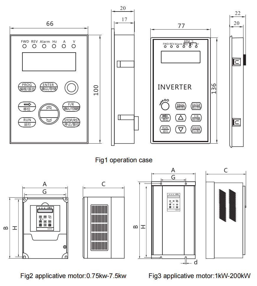
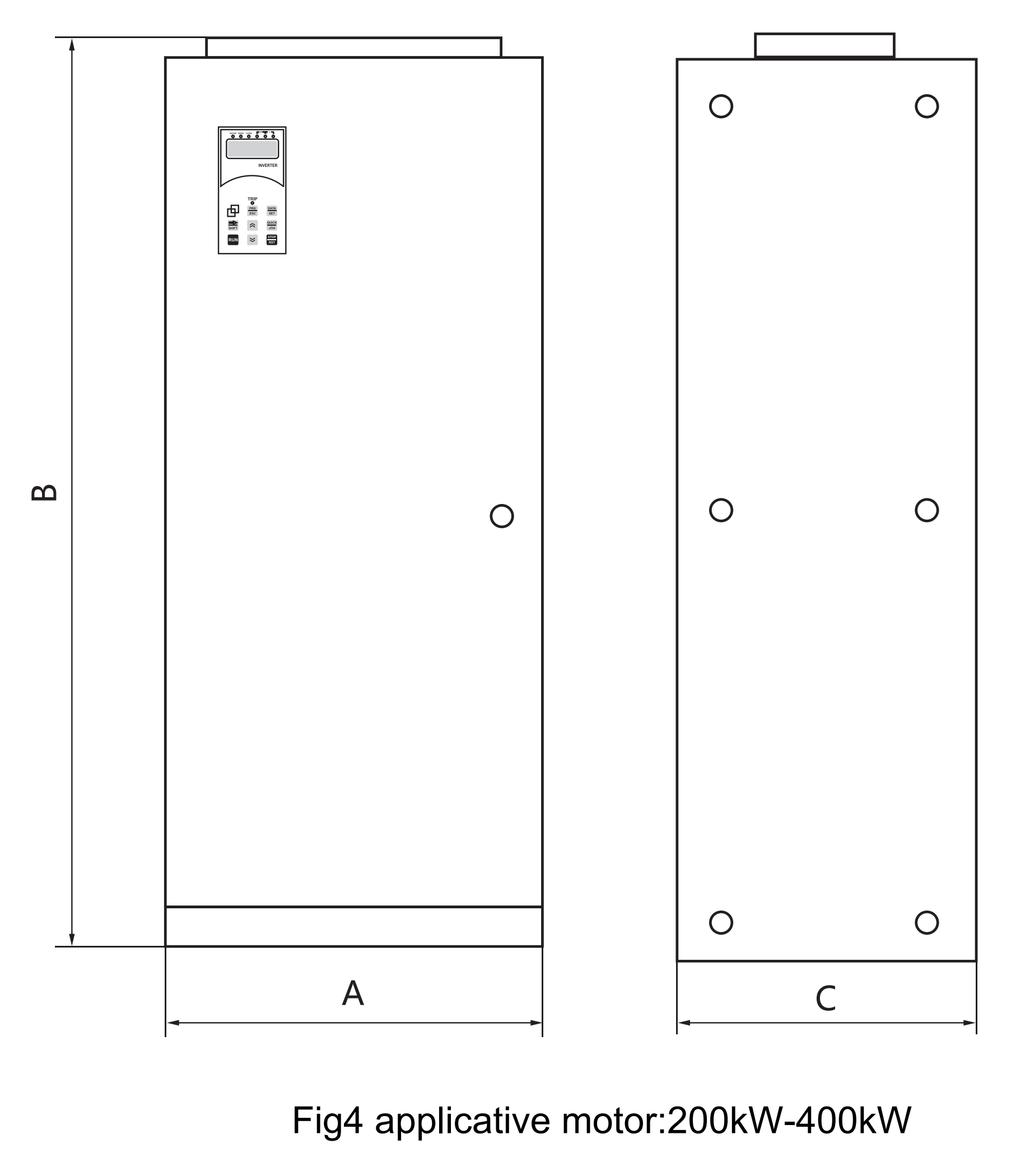
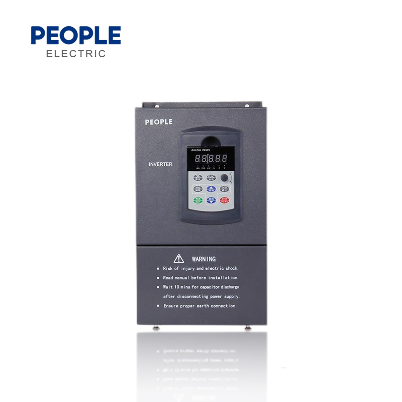
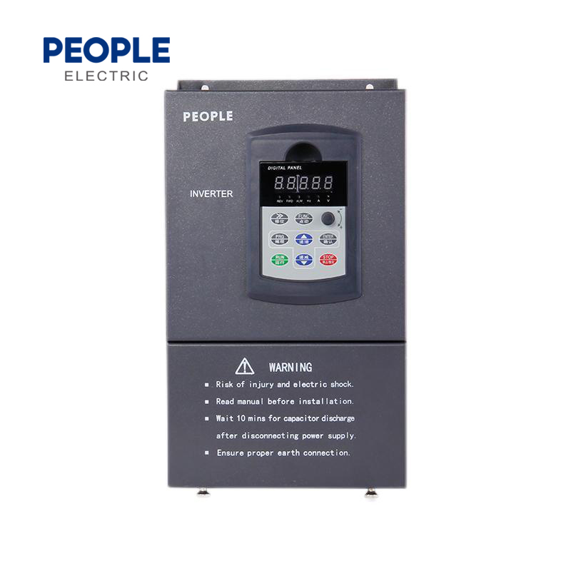
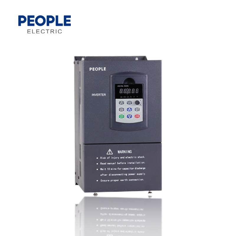
Shape size see fig2,fig3, fig4,operation case shape see fig 1.


| Adaptation of standard motors (KW) | Inverter model | Size(mm) | |||||
| 220V series | A | B | C | G | H | The safety bolt | |
| 0.75-2.2 | 0.75kV-2.2kW | 125 | 170 | 165 | 112 | 160 | M4 |
| 3.7-4 | 3.7kW-4kW | 150 | 220 | 175 | 137 | 205 | M5 |
| Adaptation of standard motors (KW) | Inverter model | Drawing number | Size(mm) | |||||
| 380V series | A | B | C | G | H | The safety bolt | ||
| 0.75-2.2 | 0.75kW-2.2kW | Figure 1 | 160 | 90 | 132.5 | 81 | 147 | M4 |
| 3.7-7.5 | 3.7kW-7.5kW | Figure 2 | 240 | 140 | 178 | 130 | 230 | M5 |
| 11-15 | 11kW-15kW | Figure 3 | 357 | 200 | 205 | 152 | 330 | M8 |
| 18.5-30 | 18.5kW-30kW | 450 | 270 | 205 | 195 | 425 | M10 | |
| 37-55 | 37kW-55kW | 560 | 320 | 275 | 240 | 535 | M10 | |
| 75-110 | 75kW-110kW | 665 | 380 | 275 | 240 | 640 | M10 | |
| 132-200 | 132kW-200kW | 775 | 500 | 290 | 360 | 738 | M10 | |
| 220 | 220kW-280kW | Figure 4 | 700 | 1350 | 417 | Console cabinet installation | ||
| 250 | ||||||||
| 280 | ||||||||
| 315 | 315kW-400kW | 1000 | 2000 | 600 | ||||
| 350 | ||||||||
| 400 | ||||||||
Specification
Voltage type: 380V and 220V
Applicative Motor capacity: 0.75kW to 315kW
Specification see Table1
| Voltage | Model No. | Rated capacity (kVA) | Rated output current (A) | Applicative motor (kW) |
| 380V three-phase |
RDI67-0.75G-A3 | 1.5 | 2.3 | 0.75 |
| RDI67-1.5G-A3 | 3.7 | 3.7 | 1.5 | |
| RDI67-2.2G-A3 | 4.7 | 5.0 | 2.2 | |
| RDI67-4G-A3 | 6.1 | 8.5 | 4.0 | |
| RDI67-5.5G/7.5P-A3 | 11 | 13 | 5.5 | |
| RDI67-7.5G/11P-A3 | 14 | 17 | 7.5 | |
| RDI67-11G/15P-A3 | 21 | 25 | 11 | |
| RDI67-15G/18.5P-A3 | 26 | 33 | 15 | |
| RDI67-18.5G/22P-A3 | 31 | 39 | 18.5 | |
| RDI67-22G/30P-A3 | 37 | 45 | 22 | |
| RDI67-30G/37P-A3 | 50 | 60 | 30 | |
| RDI67-37G/45P-A3 | 61 | 75 | 37 | |
| RDI67-45G/55P-A3 | 73 | 90 | 45 | |
| RDI67-55G/75P-A3 | 98 | 110 | 55 | |
| RDI67-75G/90P-A3 | 130 | 150 | 75 | |
| RDI67-93G/110P-A3 | 170 | 176 | 90 | |
| RDI67-110G/132P-A3 | 138 | 210 | 110 | |
| RDI67-132G/160P-A3 | 167 | 250 | 132 | |
| RDI67-160G/185P-A3 | 230 | 310 | 160 | |
| RDI67-200G/220P-A3 | 250 | 380 | 200 | |
| RDI67-220G-A3 | 258 | 415 | 220 | |
| RDI67-250G-A3 | 340 | 475 | 245 | |
| RDI67-280G-A3 | 450 | 510 | 280 | |
| RDI67-315G-A3 | 460 | 605 | 315 | |
| 220V single-phase |
RDI67-0.75G-A3 | 1.4 | 4.0 | 0.75 |
| RDI67-1.5G-A3 | 2.6 | 7.0 | 1.2 | |
| RDI67-2.2G-A3 | 3.8 | 10.0 | 2.2 |
Single phase 220V series
| Applicative motor (kW) | Model No. | Diagram | Dimension: (mm) | |||||
| 220 series | A | B | C | G | H | intall bolt | ||
| 0.75~2.2 | 0.75 kW~2.2kW | Fig2 | 125 | 171 | 165 | 112 | 160 | M4 |
Three phases380V series
| Applicative motor (kW) | Model No. | Diagram | Dimension: (mm) | |||||
| 220 series | A | B | C | G | H | intall bolt | ||
| 0.75~2.2 | 0.75kW~2.2kW | Fig2 | 125 | 171 | 165 | 112 | 160 | M4 |
| 4 | 4kW | 150 | 220 | 175 | 138 | 208 | M5 | |
| 5.5~7.5 | 5.5kW~7.5kW | 217 | 300 | 215 | 205 | 288 | M6 | |
| 11 | 11kW | Fig3 | 230 | 370 | 215 | 140 | 360 | M8 |
| 15~22 | 15kW~22kW | 255 | 440 | 240 | 200 | 420 | M10 | |
| 30~37 | 30kW~37kW | 315 | 570 | 260 | 230 | 550 | ||
| 45~55 | 45kW~55kW | 320 | 580 | 310 | 240 | 555 | ||
| 75~93 | 75kW~93kW | 430 | 685 | 365 | 260 | 655 | ||
| 110~132 | 110kW~132kW | 490 | 810 | 360 | 325 | 785 | ||
| 160~200 | 160kW~200kW | 600 | 900 | 355 | 435 | 870 | ||
| 220 | 200kW~250kW | Fig4 | 710 | 1700 | 410 | Landing cabinet installation | ||
| 250 | ||||||||
| 280 | 280kW~400kW | 800 | 1900 | 420 | ||||
| 315 | ||||||||
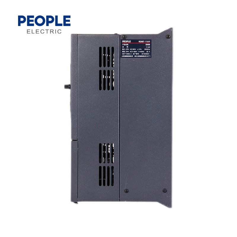
Appearance and mounting dimension
Shape size see Fig2, Fig3, Fig4, operation case shape see Fig1