


1.Ambient temperature:+5℃~+40℃, average temperature within 24h does not exceed +35℃
2.Altitude: does not exceed 2000m
3.Atmospheric condition: when the highest temperature is +40℃, the relatively humidity does not exceed 50%: it can allow relatively high humidity when it is at relatively low temperature, for instance, it reaches 90% when it is at +20℃, it should take measurement when there have condensation occurred due to the temperature variation
4.Pollution grade: 3
5.Installation category:Ⅲ
6.Installation position: the gradient of the mounting surface to the vertical surface does not exceed ±5°
7.Impact and vibration: product should be installed and used at the places without obvious shake impact and vibration
Main specification
Rated current:115,150,185,225,265,330,400,500,630,780A
Rated control power voltage of coil Us:Ac 50Hz,36,48,110,220,380,415,440,660V(special voltage can be customized)
Main parameter and technical performance index of contactor to see table 1
| Model(Table 1) | CJX2-115 | CJX2-150 | CJX2-185 | CJX2-225 | CJX2-265 | CJX2-330 | CJX2-400 | CJX2-500 | CJX2-630 | CJX2-780 | |||
| Main contacts |
Conventional heating current(≤40℃) Ith A | 200 | 200 | 275 | 275 | 315 | 380 | 450 | 630 | 800 | 1500 | ||
| Rated current (A) | AC-3 | 380V | 115 | 150 | 185 | 225 | 265 | 330 | 400 | 500 | 630 | 780 | |
| Max. power of controllable three-phase squirrel cage type motor kW | AC-3 | 380V | 63 | 80 | 100 | 110 | 140 | 180 | 200 | 250 | 335 | 400 | |
| 660V | 80 | 100 | 110 | 129 | 160 | 220 | 280 | 335 | 450 | 470 | |||
| 1000V | 63 | 75 | 100 | 132 | 160 | 200 | 250 | 300 | 450 | 450 | |||
| Operation frequency times/h (AC-3) | 1200 | 600 | |||||||||||
| Electrical life (100000 times/h) (AC-3) | 120 | 100 | |||||||||||
| Mechanical life (10000 times/h) | 1000 | 600 | |||||||||||
| Coil | Control voltage Us | AC 36,48,110,220,380,415,440,660V | |||||||||||
| Pull-in voltage 50/60Hz V | (0.85~1.1)Us | ||||||||||||
| Release voltage 50/60Hz V | (0.2~0.7)Us | ||||||||||||
| Coil power | 50Hz | Pull-in VA | 660 | 660 | 966 | 966 | 840 | 840 | 1380 | 1380 | 2076 | 2100 | |
| Hold VA | 54 | 54 | 66 | 66 | 12 | 12 | 22 | 24 | 30 | 50 | |||
| Suited fuse (SCPD) | Model | RDT16 (NT)-1 |
RDT16 (NT)-1 |
RDT16 (NT)-2 |
RDT16 (NT)-2 |
RDT16 (NT)-2 |
RDT16 (NT)-3 |
RDT16 (NT)-3 |
RDT16 (NT)-3 |
RDT16 (NT)-3 |
RDT16 (NT)-4 |
||
| Rated current | 200 | 250 | 315 | 315 | 400 | 500 | 500 | 500 | 630 | 1000 | |||
| Auxiliary contacts | Can be added with F4, LA2-D/LA3-D type air delay contacts | ||||||||||||
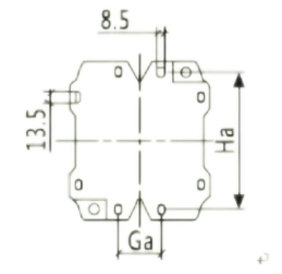
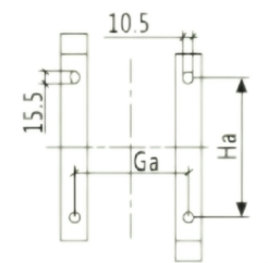
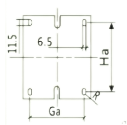
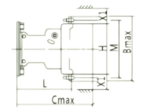
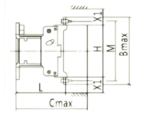
Overall dimension and installation dimension to see table 2 and fig 1~4
| mm(Table 2) | CJX2-115 | CJX2-150 | CJX2-185 | CJX2-225 | CJX2-265 | CJX2-330 | CJX2-400 | CJX2-500 | CJX2-630 | |||||||||
| 3P | 4P | 3P | 4P | 3P | 4P | 3P | 4P | 3P | 4P | 3P | 4P | 3P | 4P | 3P | 4P | 3P | 4P | |
| A max | 167 | 204 | 167 | 204 | 170 | 211 | 170 | 211 | 202 | 247 | 218 | 261 | 215 | 261 | 235 | 288 | 310 | 389 |
| B max | 163 | 163 | 171 | 171 | 175 | 175 | 175 | 175 | 203 | 203 | 210 | 210 | 210 | 210 | 240 | 240 | 304 | 304 |
| C max | 172 | 172 | 172 | 172 | 183 | 183 | 183 | 183 | 215 | 215 | 223 | 223 | 223 | 223 | 235 | 235 | 257 | 257 |
| P | 37 | 37 | 40 | 40 | 40 | 40 | 48 | 48 | 48 | 48 | 48 | 48 | 48 | 48 | 55 | 55 | 80 | 80 |
| S | 20 | 20 | 20 | 20 | 20 | 20 | 25 | 25 | 25 | 25 | 25 | 25 | 25 | 25 | 30 | 30 | 40 | 40 |
| Ø | M6 | M6 | M8 | M8 | M8 | M8 | M10 | M10 | M10 | M10 | M10 | M10 | M10 | M10 | M10 | M10 | M12 | M12 |
| f | 131 | 131 | 131 | 131 | 131 | 131 | 131 | 131 | 147 | 147 | 147 | 147 | 147 | 147 | 150 | 150 | 181 | 181 |
| M | 147 | 147 | 150 | 150 | 154 | 154 | 172 | 172 | 178 | 178 | 181 | 181 | 181 | 181 | 208 | 208 | 264 | 264 |
| H | 124 | 124 | 124 | 124 | 127 | 127 | 127 | 127 | 147 | 147 | 158 | 158 | 158 | 158 | 172 | 172 | 202 | 202 |
| L | 107 | 107 | 107 | 107 | 113.5 | 113.5 | 113.5 | 113.5 | 141 | 141 | 145 | 145 | 145 | 145 | 146 | 146 | 155 | 155 |
| X1 200~500V | 10 | 10 | 10 | 10 | 10 | 10 | 10 | 10 | 10 | 10 | 10 | 10 | 15 | 15 | 15 | 15 | 20 | 20 |
| X1 660~1000V | 15 | 15 | 15 | 15 | 15 | 15 | 15 | 15 | 15 | 15 | 15 | 15 | 20 | 20 | 20 | 20 | 30 | 30 |
| Ga | 80 | 80 | 80 | 80 | 80 | 80 | 80 | 80 | 96 | 96 | 96 | 96 | 80 | 80 | 80 | 80 | 180 | 180 |
| Ha | 106~119 | 106~119 | 106~119 | 106~119 | 106~119 | 106~119 | 170~180 | 170~180 | 180~190 | |||||||||
Note:1.f:Min.distance required by each coil.
2. X1: the arcing distance which is determined by the rated voltage and breaking capacity.


4.1 Main specification
4.1.1 Current: 115,150,185,225,265,330,400,500,630A
4.1.2 Rated control power voltage of contactor’s coil Us: AC 50Hz, 110, 127, 220, 380, 415, 440Vspecial voltage can be customized.
42 Main technique parameter of contactor
4.2.1 Characteristics of action
Pull-in voltage 85%~110%Us
Release voltage CJX2-115~265 s 20%~75% Us
4.2.2 Main parameter and technique performance index of contactor to see table l
| Model | Setting thermal current A | Rated operating current A | Controllable maximum power of three phase squirrel cage type motor KW | Operation cycling frequency times/h (AC-3) |
Electrical life when AC-3 ten thousand times | Mechanical life (ten thousand times) |
Suited fuse (SCPD) | |||||
| AC-3 | AC-3 | Model | Rated current | |||||||||
| 380V | 660V | 1000V | 380V | 660V | 1000V | |||||||
| CJX2-115 | 200 | 115 | 86 | 46 | 63 | 80 | 63 | 1200 | 120 | 1000 | RT16-2 | 250 |
| CJX2-150 | 200 | 150 | 108 | 50 | 80 | 100 | 75 | RT16-2 | 355 | |||
| CJX2-185 | 275 | 185 | 118 | 71 | 100 | 110 | 100 | 600 | 100 | 600 | RT16-3 | 425 |
| CJX2-225 | 275 | 225 | 137 | 90 | 110 | 129 | 132 | RT16-3 | 500 | |||
| CJX2-265 | 315 | 265 | 170 | 112 | 140 | 160 | 160 | / | RT16-3 | 630 | ||
| CJX2-330 | 380 | 330 | 235 | 155 | 180 | 220 | 200 | RT16-4 | 800 | |||
| CJX2-400 | 450 | 400 | 303 | 200 | 200 | 280 | 250 | RT16-4 | 800 | |||
| CJX2-500 | 630 | 500 | 353 | 232 | 250 | 335 | 300 | RT16-4 | 1000 | |||
| CJX2-630 | 800 | 630 | 462 | 331 | 335 | 450 | 475 | RT16-4 | 1250 | |||
4.2.3 Model specification and parameter of auxiliary contact group to see table 2
| Model of auxiliary contact group |
Quantity of contact | Rated insulation voltage V | Control capacity | Simple map | ||||||||
| Quantity of NO contact |
Quantity of NC contact |
|||||||||||
| F4-11 | 1 | 1 | 690 | AC-15 360VA DC-13 33w |
 |
|||||||
| F4-20 | 2 | 0 | ||||||||||
| F4-02 | 0 | 2 | ||||||||||
| F4-22 | 2 | 2 | ||||||||||
| F4-13 | 1 | 3 | 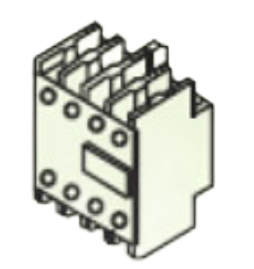 |
|||||||||
| F4-40 | 4 | 0 | ||||||||||
| F4-04 | 0 | 4 | ||||||||||
| F4-31 | 3 | 1 | ||||||||||
4.3 Main specification code of coil to see table 3
 |
AC-115~225:50Hz AC-265~630:40~400Hz | Power VA | Simple map | |||||||||
| 110 | 127 | 220 | 380 | Start up | Keeping | |||||||
| CJX2-115,150 | FF110 | FF127 | FF220 | FF380 | 660 | 54 | 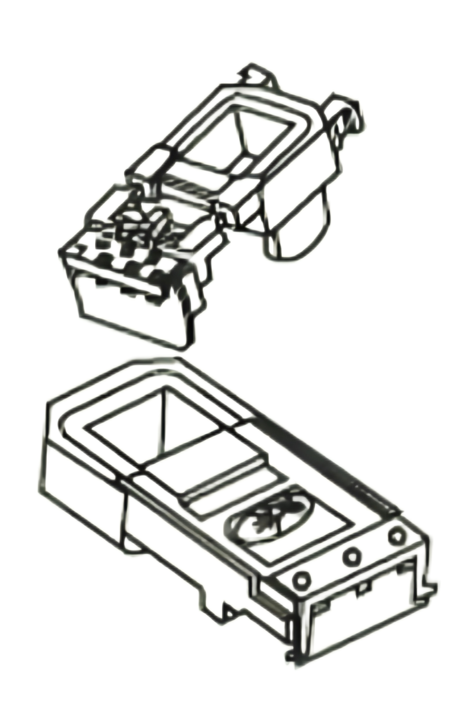 |
|||||
| CJXW-185/225 | FG110 | FG127 | FG220 | FG380 | 966 | 66 | ||||||
| CJX2-265/330 | FH110 | FH127 | FH220 | FH380 | 840 | 12 | ||||||
| CJX2-400 | FJ110 | FJ127 | FJ220 | FJ380 | 1380 | 24 | ||||||
| CJX2-500 | FK110 | FK127 | FK220 | FK380 | 1380 | 24 | ||||||
| CJX2-630 | FL110 | FL127 | FL220 | FL380 | 2076 | 30 | ||||||
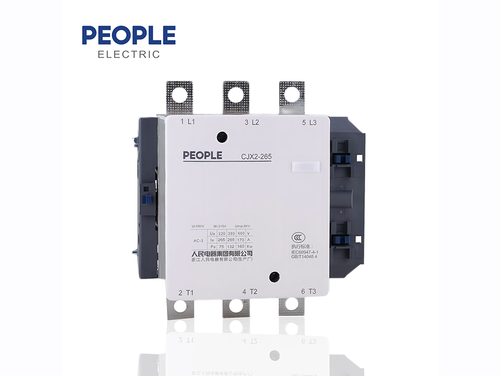
6.1 Contactor is mainly comprised of arcing system, contact system,baseand magnetic systeninclude iron core and coil) to see figure 1
| In picture: | |
| 1 .Arcing systemn | |
| 2.Contact syster | |
| 3.Base | |
| 4.Magnetic system |
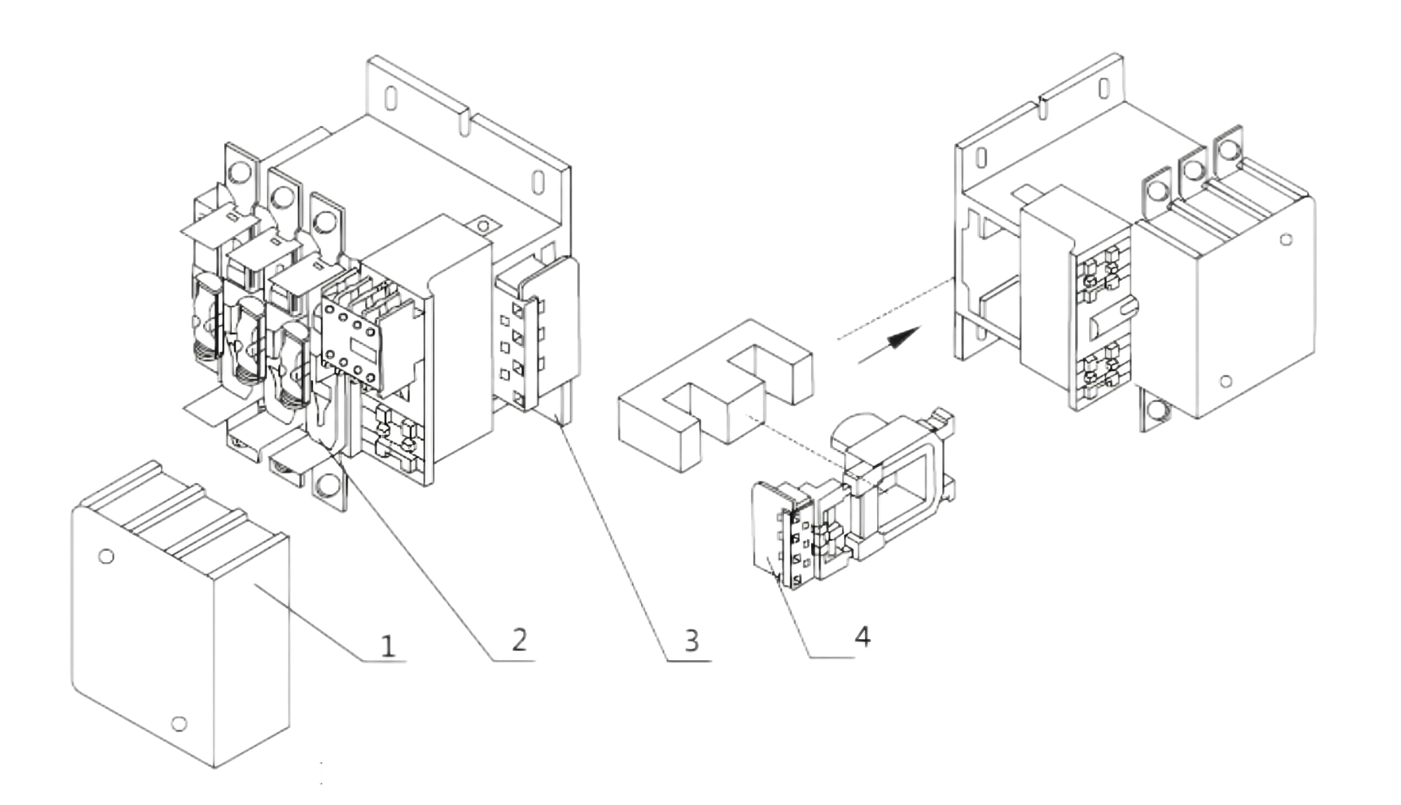
Figure 1 General structure sketch map for CJX2-115~265 contactor
6.2 Contact system of the contactor is direct-acting, double breakpoint arrangement, the lower bastdopts the aluminum alloy material, the coil is the plastic sealing structure, and the coil is combined with a magnetic yoke into a whole, which can be directly taken out or placed in, it’s very convenient and maintenance. to see figure 1
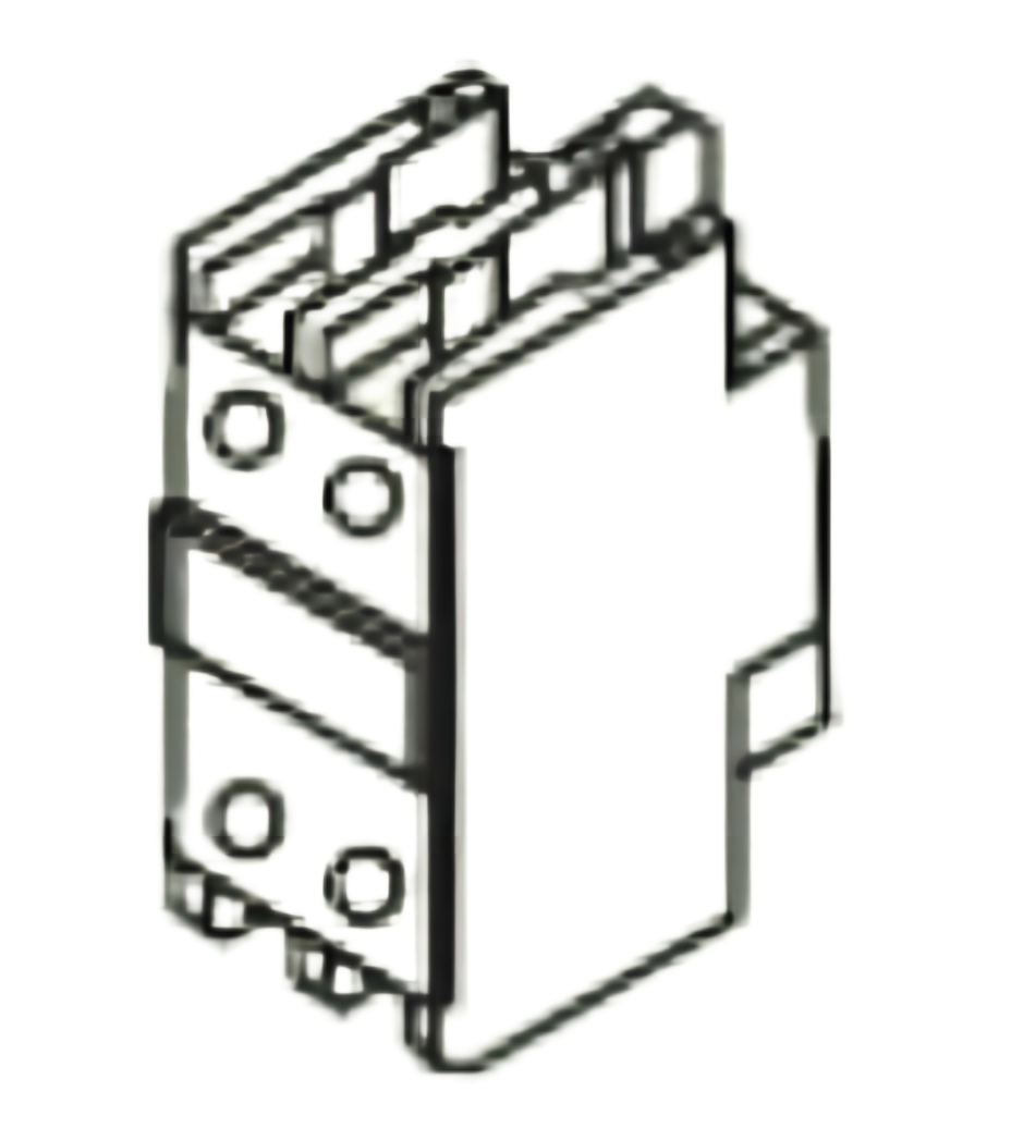
6.3 There are one couple of NO contacts inside the coil of contactor, which can be used as auto-local contact or signal contact; Additionally, it can be attached to equip with two auxiliary contact groups total of 8 couples contacts, see map 2. Combination information of auxiliary contact to see table 2
6.4 Small arcing distance of contactor, for example, the arcing distance of CIX2-115-330 is nearly 10mm (200-500V), which is one-sixth of another same capacity contactor. It is used for complete equipment can reduce the usage space, and is an excellent supporting component in power electric control equipment
6.5 It can be attached the auxiliary contact group, air delay contact, and other accessory by building block type installation mode to see Figure 2
6.6 Contactor can be attached with horizontal or vertical mechanical interlock and reciprocal interlocletween two pcs of vertical installation contactor.
6.7 Derivable two/four poles contactor
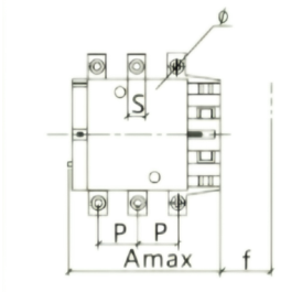
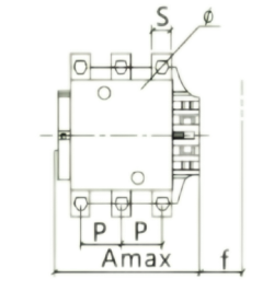
5.1 External dimension and installation dimension of contactor to see table 4
| CJX2-115~330 | CJX2-400~500 | CJX2-630 |
 |
 |
 |
 |
 |
 |
 |
 |
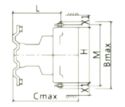 |
| Unit:mm | CJX2-115 | CIX2-150 | CJX2-185 | CJX2-225 | CJX2-265 | CJX2-330 | CJX2-400 | CJX2-500 | CJX2-630 | |||||||||||||
| 3 poles | 4 poles | 3 poles | 4 poles | 3 poles | 4 poles | 3 poles | 4 poles | 3 poles | 4 poles | 3 poles | 4 poles | 2 poles | 3 poles | 4 poles | 2 poles | 3 poles | 4 poles | 2 poles | 3 poles | 4 poles | ||
| A | 167 | 204 | 167 | 204 | 171 | 211 | 171 | 211 | 202 | 247 | 213 | 261 | 213 | 213 | 261 | 233 | 233 | 288 | 309 | 309 | 309 | |
| B | 163 | 163 | 171 | 171 | 174 | 174 | 197 | 197 | 203 | 203 | 206 | 206 | 206 | 206 | 206 | 238 | 238 | 238 | 304 | 304 | 304 | |
| C | 172 | 172 | 172 | 172 | 183 | 183 | 183 | 183 | 215 | 215 | 220 | 220 | 220 | 220 | 220 | 233 | 233 | 233 | 256 | 256 | 256 | |
| P | 37 | 37 | 40 | 40 | 40 | 48 | 48 | 48 | 48 | 48 | 48 | 48 | 48 | 48 | 48 | 55 | 55 | 55 | 80 | 80 | 80 | |
| S | 20 | 20 | 20 | 20 | 20 | 20 | 25 | 25 | 25 | 25 | 25 | 25 | 25 | 25 | 25 | 30 | 30 | 30 | 40 | 40 | 40 | |
| Φ | M6 | M6 | M8 | M8 | M8 | M8 | M10 | M10 | M10 | M10 | M10 | M10 | M10 | M10 | M10 | M10 | M10 | M10 | M12 | M12 | M12 | |
| f① | 131 | 131 | 131 | 131 | 131 | 131 | 131 | 131 | 147 | 147 | 147 | 147 | 146 | 146 | 146 | 150 | 150 | 150 | 181 | 181 | 181 | |
| M | 147 | 147 | 150 | 150 | 154 | 154 | 174 | 174 | 178 | 178 | 181 | 181 | 181 | 181 | 181 | 208 | 208 | 208 | 264 | 264 | 264 | |
| H | 124 | 124 | 124 | 124 | 127 | 127 | 127 | 127 | 147 | 147 | 158 | 158 | 158 | 158 | 158 | 172 | 172 | 172 | 202 | 202 | 202 | |
| L | 107 | 107 | 107 | 107 | 113.5 | 113.5 | 113.5 | 113.5 | 141 | 141 | 145 | 145 | 145 | 145 | 145 | 146 | 146 | 146 | 155 | 155 | 155 | |
| X1② 200~500V 660~1000V |
10 | 10 | 10 | 10 | 10 | 10 | 10 | 10 | 10 | 10 | 10 | 10 | 10 | 10 | 10 | 10 | 10 | 10 | 20 | 20 | 20 | |
| 15 | 15 | 15 | 15 | 15 | 15 | 15 | 15 | 15 | 15 | 15 | 15 | 15 | 15 | 15 | 15 | 15 | 15 | 30 | 30 | 30 | ||
| Ga | 80 | 96 | 80 | 140 | 180 | 240 | ||||||||||||||||
| Ha | 110~120 | 170~180 | 180~190 | |||||||||||||||||||
Note:
1) Assemble and disassemble the coil required minimum distance Arcing distance according to the operating voltage and breaking capacity.