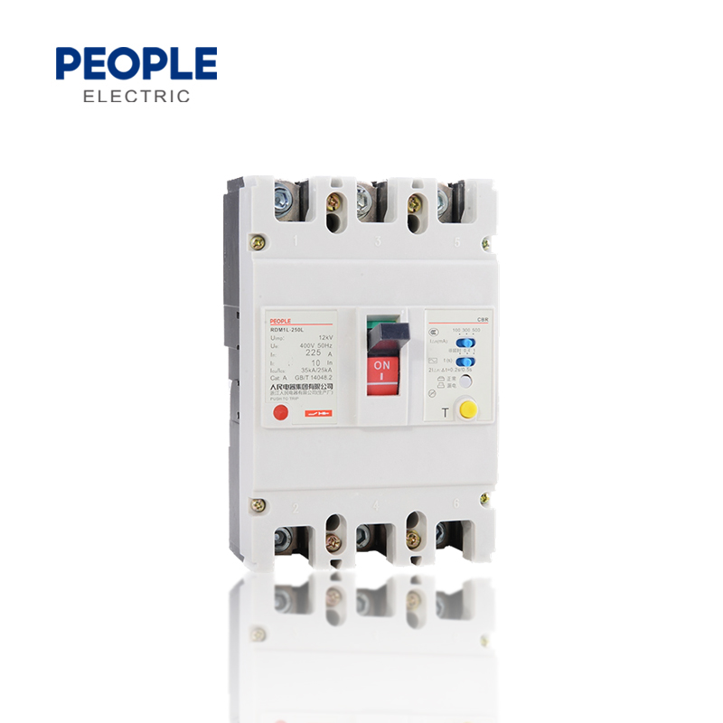
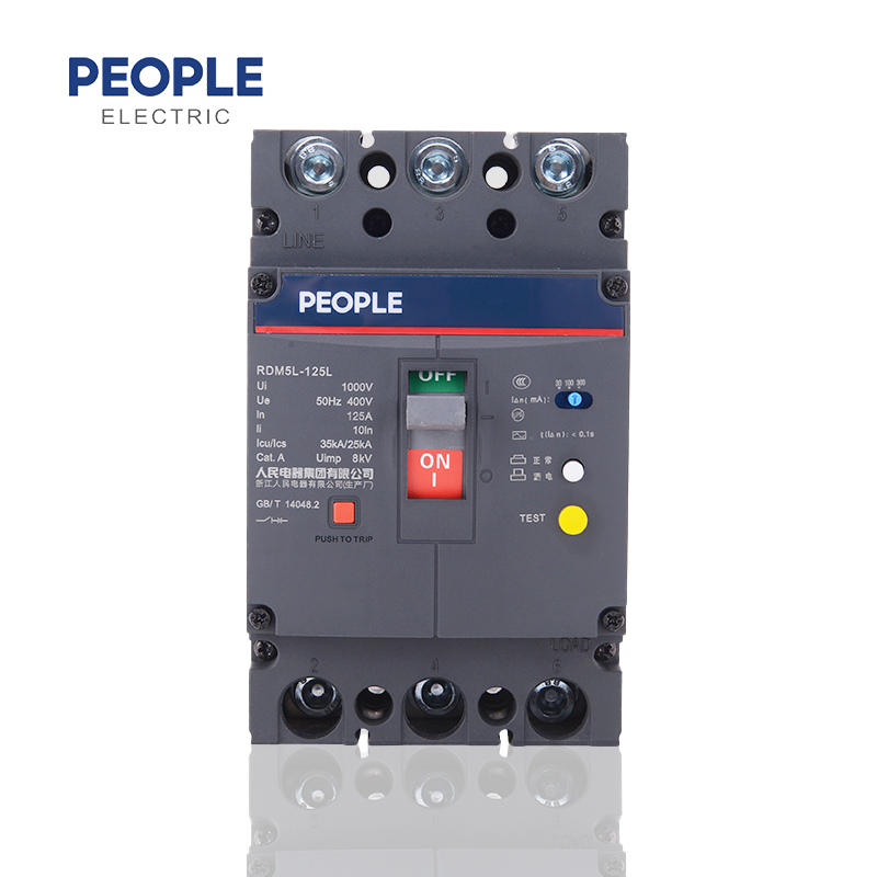
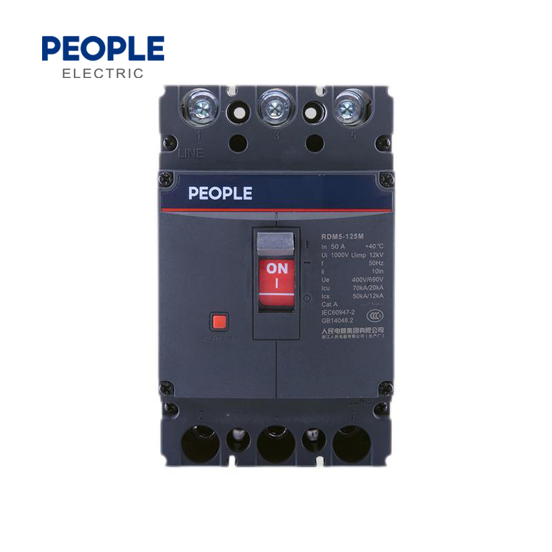
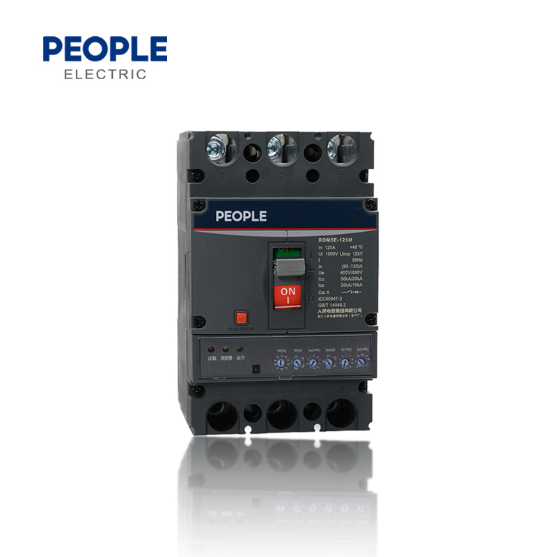
● Standard
IEC/EN 60947-1(General) GB/T 14048.1
IEC/EN60947-2(Circuit-breakers) GB/T 14048.2
IEC/EN60947-3(Switches,Isolators) GB/T 14048.3
IEC/EN60947-4(Motors and drives) GB/T 14048.4
● Compact Design
The product features a compact design: for example, a 160-frame product has dimensions equivalent to the original 100-frame model, meeting customers specific requirements for installation dimensions.
● Uniform Dimensions
Within the same frame size, products with different breaking capacities (C,S, M. H) and different functions (air, ground fault, and adjustable thermomagnetic) have completely identical installation dimensions.
● Reasonable Setting of Functional Parameters
The circuit breaker allows for the adjustment of protection parameters such as long-time inverse-time overload protection and instantaneous short-circuit tripping. Users can independently configure the required protection characteristics, enabling more rational upstream and downstream configuration of circuit breakers in power distribution networks.
1.The product has passed environmental tests including dry cold, dry heat, and damp heat, ensuring reliable operation in non-standard environments.
2.The product meets the test requirements of GB/T 2423. 1 (Low-Temperature Testing of Electrical and Electronic Products) and GB/T 2423.2 (High-Temperature Testing of Electrical and Electronic Products), and can be used within a temperature range of -35°C to 70°C. When the temperature is below -5°C or above 40°C,calculations must be performed using the temperature compensation coefficient table provided in the catalog.
3.The normal operating altitude is 2000 m or below. At altitudes exceeding 2000 m, factors such as reduced dielectric strength and colder air must be considered; please apply corrections using the altitude-dependent derating factor table provided in the catalog.
4.The product can operate reliably in pollution degree 3 environments as defined by IEC/EN 60947-1 and IEC60664-1(industrial environments).
5.The product complies with the requirements of the IEC 60529/GB/T 4208 (Enclosure ProtectionRating)standard. Product body: Protection rating is IP30 (excluding terminal blocks).
6.It can be installed vertically (upright) or horizontally (sideways).
| Product Code | Adjustable Type | Frame Class | Breaking Capacity | ||||
| RDM5 | RT | 160 | C | ||||
| Molded-case circuit breaker |
RT stands for thermomagnetically adjustable T/A stands for single adjustable(i,e., thermally adjustable/magnetically fixed(Fixed)) |
C | S | M | H | ||
| 160 | 160 | 25/15 | 35/25 | 50/35 | / | ||
| 250 | 250 | 25/18 | 35/25 | 50/35 | / | ||
| 630 | 630 | / | 35/25 | 50/35 | 70/50 | ||
| 800 | 800 | / | 35/25 | 50/35 | 70/50 | ||
| Operating Method | Poles | Trip Mechanism and Internal Components | Rated Current A | |
| P | 4 | 300 | 125A | |
| P: Electric operation Z: Rotary handle W: Direct operation D: Electric operation DC1,DC2,Dc3 |
2:2-pole 3:3-pole 4:4-pole |
The first digit indicates the trip mechanism type 2: Instantaneous trip only 3: Dual-stage trip unit Note: The last two digits are the accessory code(see attachment table). |
160 | 32,40,50,63,80,100,125,140,160 |
| 250 | 100,125,140,160,180,200,225,250 | |||
| 630 | 250,315,350,400,500,630 | |||
| 800 | 500,630,700,800 | |||
| Application | Available Part Numbers For 4-pole Products |
| 2 | B |
| 1 : For power distribution 2: For motor protection |
A: N-pole without protection,cannot close or open A B: N-pole without protection,can be closed and opened |
| Accessory voltage | Motor operating voltage | Mounting method | Is a terminal block installed? | |||
| Q1 | D1 | Q | 2 | |||
| Undervoltage Trip Unit UVT |
Shunt Trip Unit | Auxiliary Alarm | DC1 | DC3 | Q:Front of board H:Rear CQ:Plug-in front panel CH:Plug-in rear panel |
Install 1:Do not install 2:Installed |
| D1:AC 220V | D5:AC 230V | |||||
| Q1:AC 220V | F1:AC 220V J1:Ac 125 |
J1:AC125V | D2:AC 230V | D6:AC 110V | ||
| Q2:AC 240V | F2:AC 380V | J2:AC 250V | D3:AC 380V | D7:DC 220 | ||
| Q3:AC 380V | F3:DC 110 V | J3:DC 125V | D4:AC 400V | D8:DC 110 | ||
| Q4:AC 415V | F4:DC 24V | J4:DC 24V | D9:AC 110-240 V | |||
| D10:DC 100-220 V | ||||||
| Note:When selecting electric operation,refer to the external accessories section. | ||||||
| Model | RDM5T/A、RT-160 | RDM5T/A、RT-250 | RDM5T/A、RT-630 | RDM5T/A、RT-800 | ||
| Breaking Capacity | C,S,M | C,S,M | S,M,H | S,M,H | ||
| Pole | 3,4 | 3,4 | 3,4 | 3,4 | ||
| Attachment Code | Attachment Name | |||||
| 208,308 | Alarm switch | 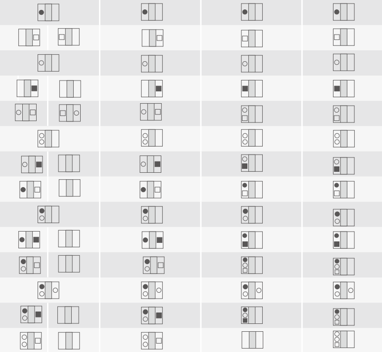 |
||||
| 210,310 | Shunt Trip Unit | |||||
| 220,320 | Auxiliary switch | |||||
| 230,330 | Undervoltage release |
|||||
| 240,340 | Shunt trip unit and auxiliary switch | |||||
| 260,360 | Two sets of auxiliary switches | |||||
| 270,370 | Auxiliary switch,undervoltage trip unit | |||||
| 218,318 | Shunt trip unit and alarm Switch | |||||
| 228,328 | Auxiliary switch Alarm switch | |||||
| 238,338 | Undervoltage trip unit alarm switch | |||||
| 248,348 | Shunt trip unit,auxiliary switch,alarm switch | |||||
| 268,368 | Two sets of auxiliary switches and alarm switches | |||||
| 278,378 | Auxiliary switch undervoltage trip unit,alarm switch | |||||
| 280,380 | Two sets of auxiliary switch shunt trip units | |||||

⚫Alarm Switch ◯Auxiliary Switch ⬜Shunt Trip ⬛Undervoltage Trip Unit
Note:
1. The company offers three new products-right auxiliary switch, left shunt, and left undervoltage-for customers to choose from.
2. For the 220,320,240,340,270, and 370 models, two sets of auxiliary switches are available;pleasespecify this when ordering.
| Model | RDM5T/A、RT-160 | RDM5T/A、RT-250 | ||||||
| Frame rating rated current Inm(A) | 160 | 250 | ||||||
| Number of poles | 3,4 | 3,4 | ||||||
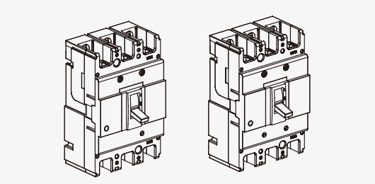
| Product Image | 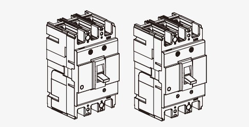 |
 |
||||||
| Rated Current In(A),40℃,50℃,55℃ | 63,80,100,125,160 | 125,140,160,180,200,225,250 | ||||||
| Rated operating voltage Ue(V),AC 50/60 Hz | 400/415 | 400/415 | ||||||
| Rated insulation voltage Ui(V) | 800 | 800 | ||||||
| Rated impulse withstand voltage Uimp(kV) | 8 | 8 | ||||||
| Breaking capacity code | C | S | M | C | S | M | ||
| Short-circuit breaking capacity Icu/Ics (kA)AC 400/415 V | 25/15 | 35/25 | 50/35 | 25/18 | 35/25 | 50/35 | ||
| Selection Category | A | A | A | A | A | A | ||
| Trip Mechanism Types and Protection Classes |
Electromagnetic trip Thermal-magnetic trip |
Power ON | 3000 | 3000 | ||||
| Power Off | 9000 | 9000 | ||||||
| Power Distribution Protection | ⚫ | ⚫ | ⚫ | ⚫ | ⚫ | ⚫ | ||
| Motor protection | ⚫ | ⚫ | ⚫ | ⚫ | ⚫ | ⚫ | ||
| Power Distribution Protection | ⚫ | ⚫ | ⚫ | ⚫ | ⚫ | ⚫ | ||
| Motor protection | ⚫ | ⚫ | ⚫ | ⚫ | ⚫ | ⚫ | ||
| Accessories | Auxiliary Contacts | ⚫ | ⚫ | ⚫ | ⚫ | ⚫ | ⚫ | |
| Alarm Contacts | ⚫ | ⚫ | ⚫ | ⚫ | ⚫ | ⚫ | ||
| Shunt Trip Unit | ⚫ | ⚫ | ⚫ | ⚫ | ⚫ | ⚫ | ||
| Undervoltage trip | ⚫ | ⚫ | ⚫ | ⚫ | ⚫ | ⚫ | ||
| Manual operating mechanism | ⚫ | ⚫ | ⚫ | ⚫ | ⚫ | ⚫ | ||
| Electric operating mechanism | ⚫ | ⚫ | ⚫ | ⚫ | ⚫ | ⚫ | ||
| Rear Panel Wiring | ⚫ | ⚫ | ⚫ | ⚫ | ⚫ | ⚫ | ||
| Plug-in | ⚫ | ⚫ | ⚫ | ⚫ | ⚫ | ⚫ | ||
| Connection plate | ⚫ | ⚫ | ⚫ | ⚫ | ⚫ | ⚫ | ||
| Phase separator | ⚫ | ⚫ | ⚫ | ⚫ | ⚫ | ⚫ | ||
| Dimensions (mm) (a-b-c-ca) |
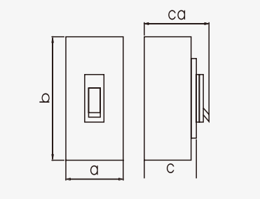 |
3-pole (3P) | 90-155-2017-95 | 90-155-84.9-109.2 | 105-165-71-95.8 | 105-165-93.4-118.6 | ||
| 4-pole (4P) | 120-155-70.7-95 | 120-155-84.9-109.2 | 140-165-71-95.8 | 140-165-93.4-118.6 | ||||
Note:Add ● indicates optional accessories, add -indicates no optional accessories.
| Model | RDM5T/A、RT-630 | RDM5T/A、RT-800 | ||||||
| Frame rating rated current Inm(A) | 630 | 800 | ||||||
| Number of poles | 3,4 | 3,4 | ||||||
| Product Image | 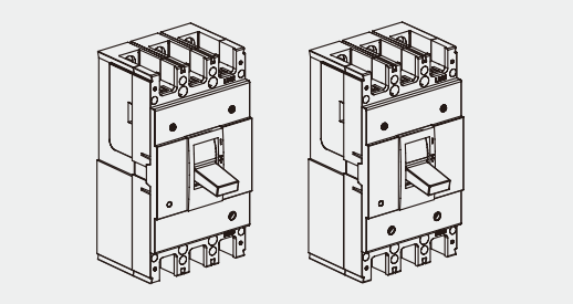 |
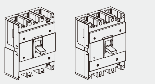 |
||||||
| Rated Current In(A),40℃,50℃,55℃ | 250,315,350,400,500,630 | 500,630,700,800 | ||||||
| Rated operating voltage Ue(V),AC 50/60 Hz | 400/415 | 400/415 | ||||||
| Rated insulation voltage Ui(V) | 800 | 800 | ||||||
| Rated impulse withstand voltage Uimp(kV) | 8 | 8 | ||||||
| Breaking capacity code | S | M | H | S | M | H | ||
| Short-circuit breaking capacity Icu/Ics (kA)AC 400/415 V | 35/25 | 50/35 | 75/50 | 35/25 | 50/35 | 75/50 | ||
| Selection Category | A | A | A | A | A | A | ||
|
Number ofoperating cycles |
Electromagnetic trip Thermal-magnetic trip |
Power ON | 3000 | 3000 | ||||
| Power Off | 9000 | 9000 | ||||||
| Power Distribution Protection | ⚫ | ⚫ | ⚫ | ⚫ | ⚫ | ⚫ | ||
| Motor protection | ⚫ | ⚫ | ⚫ | ⚫ | ⚫ | ⚫ | ||
| Power Distribution Protection | ⚫ | ⚫ | ⚫ | ⚫ | ⚫ | ⚫ | ||
| Motor protection | ⚫ | ⚫ | ⚫ | ⚫ | ⚫ | ⚫ | ||
| Accessories | Auxiliary Contacts | ⚫ | ⚫ | ⚫ | ⚫ | ⚫ | ⚫ | |
| Alarm Contacts | ⚫ | ⚫ | ⚫ | ⚫ | ⚫ | ⚫ | ||
| Shunt Trip Unit | ⚫ | ⚫ | ⚫ | ⚫ | ⚫ | ⚫ | ||
| Undervoltage trip | ⚫ | ⚫ | ⚫ | ⚫ | ⚫ | ⚫ | ||
| Manual operating mechanism | ⚫ | ⚫ | ⚫ | ⚫ | ⚫ | ⚫ | ||
| Electric operating mechanism | ⚫ | ⚫ | ⚫ | ⚫ | ⚫ | ⚫ | ||
| Rear Panel Wiring | ⚫ | ⚫ | ⚫ | ⚫ | ⚫ | ⚫ | ||
| Plug-in | ⚫ | ⚫ | ⚫ | ⚫ | ⚫ | ⚫ | ||
| Connection plate | ⚫ | ⚫ | ⚫ | ⚫ | ⚫ | ⚫ | ||
| Phase separator | ⚫ | ⚫ | ⚫ | ⚫ | ⚫ | ⚫ | ||
| Dimensions(mm) (a-b-c-ca) |
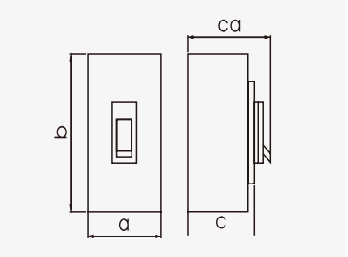 |
3-pole (3P) | 140-257-107.5-156 | 210-275-114.3-162.5 | ||||
| 4-pole (4P) | 185-257-107.5-156 | 280-275-114.3-162.5 | ||||||
Note:Add ● indicates optional accessories, add -indicates no optional accessories.
1.The inverse-time operating characteristics of distribution circuit breakers with no humidity compensation.
When all poles are energized simultaneously at an ambient air temperature of +40°C , are shown in the table below:
| Test Current Name | Setting current multiplier | Conventional Time | Initial State |
| In≤63 In>63 | |||
| Agreed non-trip current | 1.05 | ≥ 1h ≥ 2h | Cold state |
| Rated tripping current | 1.3 | <1h <2h | Hot state |
2.For motor protection circuit breakers,the inverse-time operating characteristics (without humidity compensation)
When all poles are energized simultaneously at an ambient air temperature of +40°C are shown in the table below:
| Test Current Name | Setting current multiplier | Specified Time | Initial State |
| In≤800 | |||
| Agreed non-trip current | 1.0 | ≥ 2h | Cold state |
| Rated tripping current | 1.2 | <2h | Hot state |
3.Operating characteristics under short-circuit conditions:
The short-circuit current setting of the instantaneous trip unit for distribution circuit breakers is 10 In;
For circuit breakers used for motor protection , the short-circuit current setting of the instantaneous trip unit is 12In;
The accuracy of the short-circuit current setting for the instantaneous trip unit is ±20%.
RDM5T/A、RT-160 Operating Characteristic Curve

RDM5T/A、RT-250 Operating Characteristics Curve

RDM5T/A、RT-630 Operating Characteristics Curve

RDM5T/A、RT-800 Operating Characteristics Curve


| Molded Case Circuit Breaker |
Overall Dimensions | Installation Dimensions | Bolt | |||||||||||||||||||||
| A | A1 | A2 | A3 | B | B1 | B2 | B3 | B5 | B6 | H | H1 | H2 | H3 | H4 | H5 | H6 | A4 | B4 | ||||||
| 3P | 4P | 3P | 4P | 3P | 4P | 3P | 4P | |||||||||||||||||
| RDM5 RT-160CS | 90 | 120 | 60 | 90 | - | - | - | - | 155 | 134 | 103 | 50 | 48 | - | 95 | 76 | 2.2 | 70.7 | 62.3 | 23.8 | 24.6 | 30 | 132 | M8 |
| RDM5 RT-160M | 90 | 120 | 60 | 90 | - | - | - | - | 155 | 134 | 103 | 50 | 48 | - | 109.2 | 90 | 2.2 | 84.9 | 76.4 | 23.1 | 24.9 | 30 | 132 | M8 |
| RDM5 RT-250CS | 105 | 140 | 70 | 105 | - | - | - | - | 165 | 144 | 102 | 50 | 97 | - | 95.8 | 75 | 2.8 | 71 | 62.2 | 22.7 | 23.3 | 35 | 126 | M8 |
| RDM5 RT-250M | 105 | 140 | 70 | 105 | - | - | - | - | 165 | 144 | 102 | 50 | 95 | - | 118.6 | 97.6 | 2.8 | 93.4 | 84.5 | 23.1 | 23.2 | 35 | 126 | M8 |
| RDM5RT-630 SMH 400A | 140 | 185 | 88 | 132 | 140 | 196 | 112 | 168 | 257 | 230 | 179 | 90 | 103 | 42 | 156 | 112.1 | 3.5 | 107.5 | 99.6 | 30.9 | 32 | 44 | 194 | M10 |
| RDM5RT-630 SMH 630A | 140 | 185 | 88 | 132 | 140 | 196 | 112 | 168 | 257 | 230 | 179 | 90 | 103 | 42 | 156 | 112.1 | 3.5 | 107.5 | 99.6 | 33.4 | 34 | 44 | 194 | M10 |
| RDM5RT-800 SMH 630A | 210 | 280 | 140 | 210 | 180 | 250 | 140 | 210 | 275 | 243 | 192 | 90 | 103 | 87 | 162.5 | 118.4 | 2.7 | 114.3 | 106 | 28.5 | 30.7 | 70 | 242.5 | M12 |
| RDM5RT-800 SMH 800A | 210 | 280 | 140 | 210 | 180 | 250 | 140 | 210 | 275 | 243 | 192 | 90 | 103 | 87 | 162.5 | 118.4 | 2.7 | 114.3 | 106 | 29.5 | 32.7 | 70 | 242.5 | M12 |
| RDM5RT-1250SMH | 210 | 280 | 140 | 210 | 180 | 250 | 140 | 210 | 275 | 243 | 192 | 90 | 103 | 87 | 162.5 | 118.4 | 2.7 | 114.3 | 106 | 31.5 | 34.7 | 70 | 242.5 | M10 |