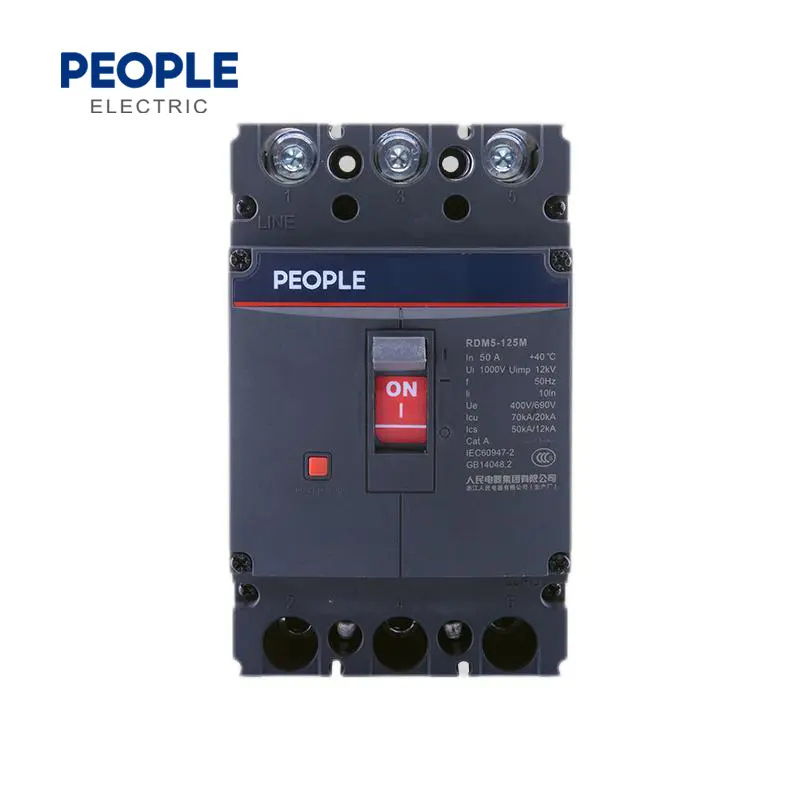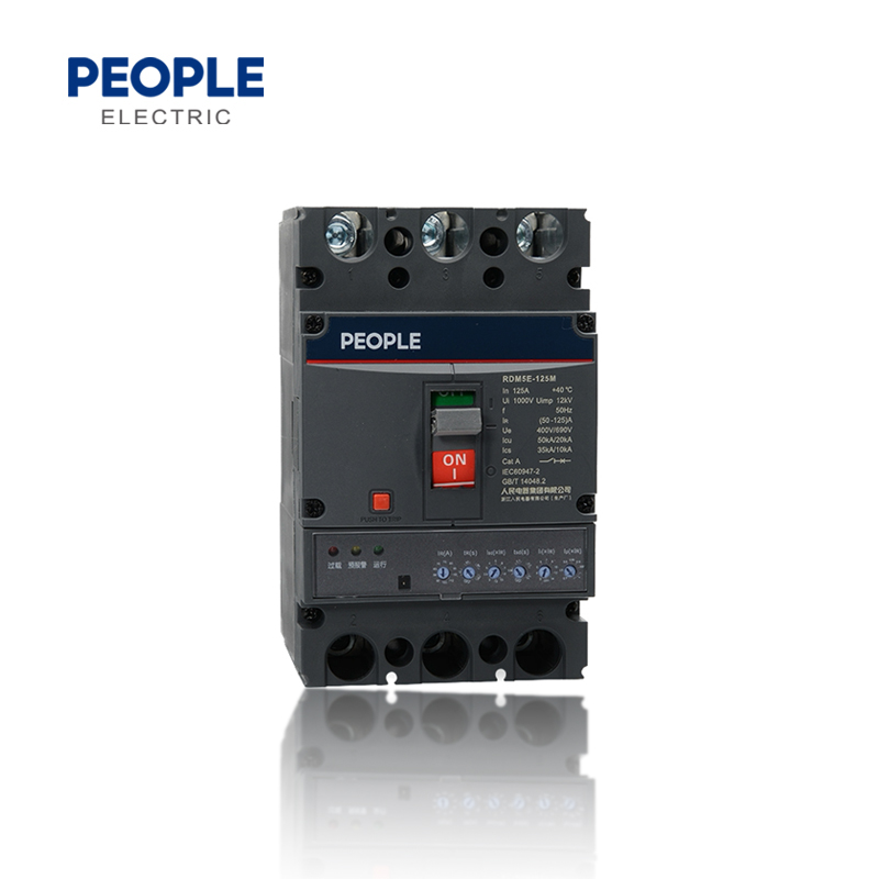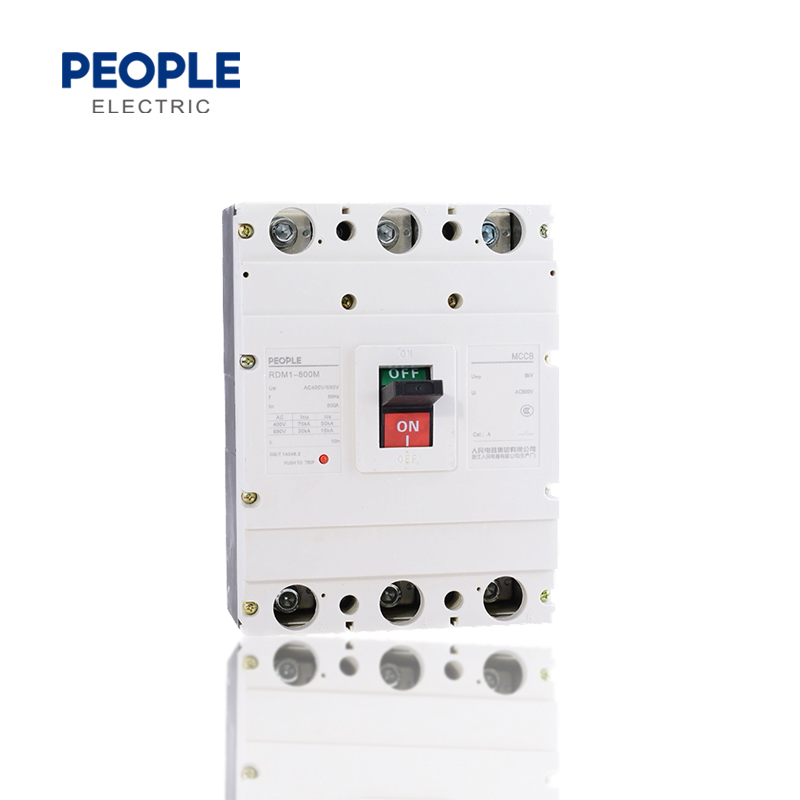


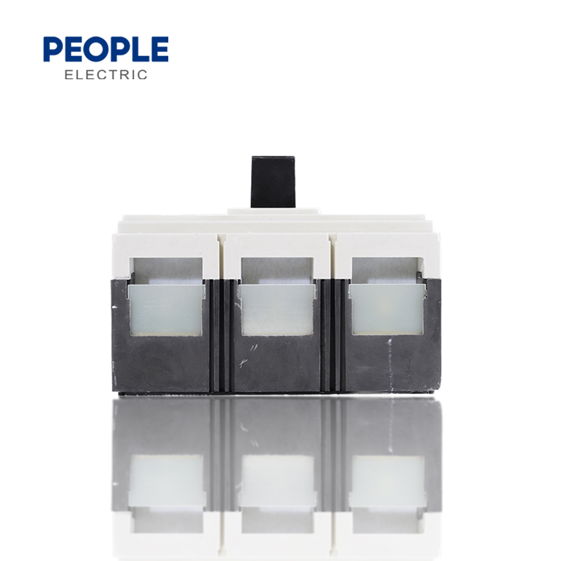
1.Advantages:small volume,high breaking capacity,short arc,anti vibration
2.It is the ideal product for land and marine use
3.Reasonable parameter setting
4.Boxed accessory design,easy installation
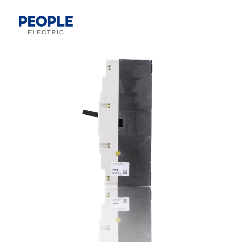
5.Compact Size

• Temperature:no higher than +40°C, and no lower than -5°C ,and the average temperature no higher than +35°C
• Installation location no more than 2000m
• The relative humidity:no more than 50%, when Temperature is +40°C. The product can withstand the higher humidity under lower temperature, for instance, when temperature at +20°C, the product can withstand 90% relative humidity.The condensation that happened because of temperature changes should be taken care in special measurements
• Class of pollution:3 Class
• Maximum install inclined Angle:22.5°
• Auxiliary circuit and control circuit installation type:Ⅱ Class; Main circuit breaker installation type:Ⅲ Class
• It can stand the normal vibration and operate stably under marine condition
| Model No. | Frame size rated current Inm A | Rated current In (A) | Rated working voltage Ue (V) | Poles | Rated short-circuit crcuit Breaker (kA) | Arc distance(mm) | |||
| Icu/ cosφ | Ics/ cos Φ | ||||||||
| 400V | 690V | 400V | 690V | ||||||
| RDM1-80L | 80 | (6), 10, 16, 20, 25, 32, 40, 50, 63, 80 | 400 | 3 | 25 | - | 12.5 | - | ≤50 |
| RDM1-80M | 400 | 3, 4 | 50 | - | 25 | - | |||
| RDM1-125L | 125 | (10), 16, 20, 25, 32, 40, 50, 63, 80, 100, 125 | 400 | 2, 3, 4 | 35 | - | 20 | - | ≤50 |
| RDM1-125M | 400/690 | 2, 3, 4 | 50 | 10 | 35 | 5 | |||
| RDM1-125H | 400/690 | 3, 4 | 85 | 20 | 50 | 10 | |||
| RDM1-250L | 250 | 100, 125, 160, 180, 200, 225, 250 | 400 | 2, 3, 4 | 35 | - | 25 | - | ≤50 |
| RDM1-250M | 400/690 | 2, 3, 4 | 50 | 10 | 35 | 5 | |||
| RDM1-250H | 400/690 | 3, 4 | 85 | 10 | 50 | 5 | |||
| RDM1-400L | 400 | 250, 315, 350, 400 | 400/690 | 3, 4 | 50 | 10 | 35 | 5 | ≤100 |
| RDM1-400M | 400/690 | 3, 4 | 65 | 10 | 42 | 5 | |||
| RDM1-400H | 400/690 | 3, 4 | 85 | 10 | 50 | 5 | |||
| RDM1-630L | 630 | 400, 500, 630 | 400 | 3, 4 | 35 | - | 25 | - | ≤100 |
| RDM1-630M | 400/690 | 3, 4 | 50 | 10 | 35 | 5 | |||
| RDM1-630H | 400 | 3, 4 | 85 | - | 50 | - | |||
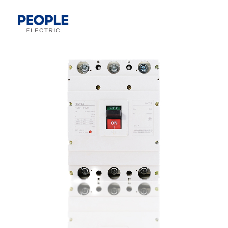
| RDM1-800M | 800 | 630, 700, 800 | 4400/690 | 3, 4 | 50 | 20 | 35 | 10 | ≤100 |
| RDM1-800H | 400 | 3, 4 | 85 | - | 50 | - | |||
| RDM1-1250M | 1250 | 700, 800, 1000, 1250 | 400/690 | 3, 4 | 65 | 20 | 35 | 10 | ≤100 |
| RDM1-1250M | 1600 | 1250, 1600 | 400/690 | 3, 4 | 65 | 20 | 35 | 10 | ≤100 |
| 4P with N-pole type | |
| Code | Structure description(Production without indicated is B type) |
| A type | N-pole without overload tripping, and N-pole is always connected |
| B type | N-pole without overload tripping, and connecting, breaking with other poles |
| Distribution circuit breaker | Motor-protection circuit breaker | ||||||
| Rated current ln (A) | Thermal relay release | Electromagnetic release operational current(A) | Rated current ln (A) | Thermal relay release | Electromagnetic release operational current(A) | ||
| 1.05ln Conventional non tripping time H(cold state) | 1.30ln Conventional tripping time H(heat state) |
1.0ln Conventional non tripping time H(cold state) | 1.2ln Conventional tripping time H(heat state) | ||||
| 10≤ln≤80 | 1 | 1 | 10ln±20% | 10≤ln≤630 | 2 | 2 | 12ln±20% |
| 80<ln≤125 | 2 | 2 | |||||
| 125<ln≤800 | 2 | 2 | 5ln±20%, 10ln±20% | ||||
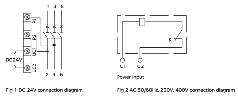
Shunt release
Connection diagram,see Fig 1 an Fig 2.
Rated voltage of control power suppy: AC 50/60Hz, 230V, 400V; DC24v, circuit breaker can operate reliably under 85% to 110% of the rated control power supply voltage.

Note:Explanation of the symbol K in Fig 2
K: Shunt release
The micro switch connected in series with the internal coil is a normally closed contact. When the circuit breaker is opened, the contact opens itself and closes when it is closed.
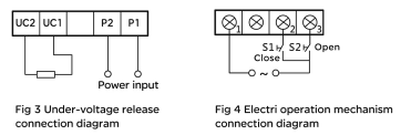
Under-voltage release
When the voltage is below 35% of the rated control power voltage, this release can prevent circuit breaker against closing. Wiring diagram, see Fig 3.
When the voltage decrease to the range of 70% to 35% of rated control power voltage, the under-voltage release would trip.
When the voltage is in the range of 85% to 110% of the rated control power voltage, this release can ensure the circuit closing reliably.
Notice: The circuit breaker with under-voltage release could trip and close, only supplied the circuit breaker with rated voltage.

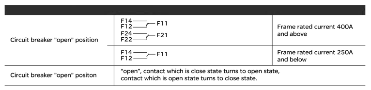
Auxiliary contact
| The auxiliary contact details | ||
| Circuit breaker "open" position |  |
Frame rated current 400A and above |
 |
Frame rated current 250A and below | |
| Circuit breaker "open" position | “open”,contact which is close state turns to open state,contact which is open state turns to close state. | |
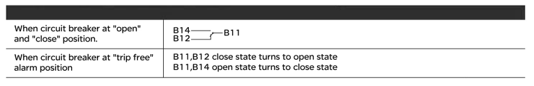
Alarm contact
Rated operational voltage's parameter, see Table 1.
| When circuit breaker is at "open'and "close" position |  |
| When circuit breaker is at "trip free'alarm position | B11,B12 close state turns to open state B11,B14 open state turns to close state  |
| Type(table 1) | Frame size rated current | Conventional heating current A | AC-15 | DC-13 | |||
| Rated operational voltage(V) | Rated frequency(Hz) | Rated current(A) | Rated operational voltage(V) | Rated current(A) | |||
| Auxiliary contacts | Inm≤250 | 3 | 400 | 50 | 0.3 | 230 | 0.15 |
| Inm≥400 | 3 | 0.4 | 0.15 | ||||
| Alarming contacts | 80≤Inm≤800 | 3 | 0.3 | 0.15 | |||
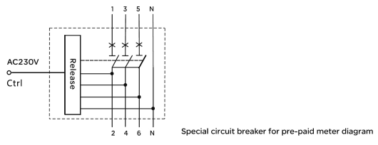
Special circuit breaker accessories Fee-controlled meter
Rated operational votage of the shunt release of Fee-controlled meter is Ac230V 50Hz, Operate in the range of 65% to 110% Ue, when the NC contacts K of the fee controlled meter is disconnected due to arrears, the circuit breaker will be delayed by 0.5-2s. The wiring diagram is as follows:

Note: Normally closed contact of K-prepaid electric energy meter
Over-voltage circuit breaker
Over-voltage circuit breaker should be tripping under following conditions:
a) When the rated operational voltage(phase voltage) Ue lower than 262v
b) When the neutral line of three phases and four wires is breaking
c) When the neutral line misconnecting phase lines
Electric operation mechanism structure see the below Table
| Type/Model | RDM1-80,125,250 | RDM1-400,630,800 |
| Structure | Electromagnet | Motor |
| Specification | 50Hz,230V.400V | 50Hz,AC110~230V,DC110~230V |
Remark: After the circuit breaker with electric operaing mechanism trips, the electric operating mechanism must make the circuit breaker buckle again before it can be closed.
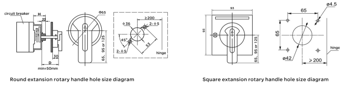
Manual operating mechanism should be installed after driling the hole according to the diagram
Rotary handle "OFF" indicated to horizontal position, keep the hande position, and try to operating the handle, the rotation should fexible, and the breaker should be open when the handle at horizontal position; and breaker should be closed when the handle at vertical position.

| Model No. | RDM1-80 | RDM1-125 | RDM1-250 | RDM1-400 | RDM1-630 | RDM1-800 |
| Installation dimension | 50 | 52 | 54 | 97 | 97 | 90 |
| Y value of the operating handle relative to the breaker Center | 0 | 0 | 0 | 0 | 0 | 0 |
Installation dimension of Mechanical interlock of two circuit breakers, see Fig 6 and Table 2

| Model No.(Table 2) | A | B | W | C | D | L | Φd |
| RDM1-80 | 25 | 117 | 105 | 35 | 22 | 117 | 3.5 |
| RDM1-125 | 30 | 129 | 120 | 46 | 22 | 140 | 4.5 |
| RDM1-250 | 35 | 126 | 138 | 46 | 22 | 132 | 5.5 |
| RDM1-400L,M,H | 44 | 194 | 178.5 | 56 | 28 | 188 | 7 |
| RDM1-630 | 58 | 200 | 230 | 56 | 28 | 240 | 7 |
| RDM1-800 | 70 | 243 | 250 | 56 | 28 | 252 | 7.5 |
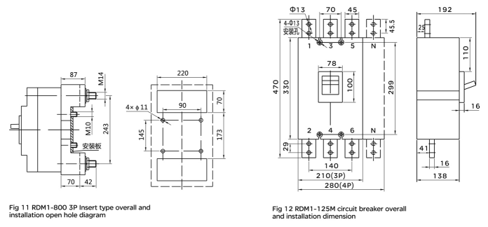
RDM1-80~800A Front wiring overall and installation board hole-opening dimension, see Fig. 12, Fig. 8 and table3

| Model No.(Table 3) | Front connection overall | Installation dimension | ||||||||||||||||||||
| W | L | H | H1 | H2 | H3 | W1 | L1 | L2 | W2 | K | N | M | X | Y | A | B | Φd | |||||
| 3P | 4P | 3P | 4P | 3P | 4P | 3P | 4P | |||||||||||||||
| RDM1-80L | 78 | - | 135 | 73 | 90.5 | 20 | 6.5 | 25 | 170 | 117 | 14 | 86.5 | 42.5 | 35 | - | 25 | - | 69 | - | 25 | 117 | 4 |
| RDM1-80M RDM1-80H |
78 | 102 | 135 | 82 | 98.5 | 28 | 6.5 | 25 | 170 | 117 | 14 | 86.5 | 41.5 | 35 | 26.5 | 25 | 23 | 69 | 49 | 25 | 117 | 4 |
| RDM1-125L | 92 | 122 | 150 | 68 | 86 | 24 | 7.5 | 30 | 200 | 132 | 17 | 89 | 43 | 32 | 27 | 27 | 23 | 67 | 51 | 30 | 129 | 4 |
| RDM1-125M RDM1-125H |
92 | 122 | 150 | 86 | 104 | 24 | 7.5 | 30 | 200 | 132 | 17 | 89 | 43 | 32 | 27 | 27 | 23 | 67 | 51 | 30 | 129 | 4 |
| RDM1-250L | 107 | 142 | 165 | 86 | 110 | 24 | 6 | 35 | 230 | 144 | 24 | 98 | 51 | 39 | 27 | 27 | 23 | 80 | 54 | 35 | 126 | 5 |
| RDM1-250M RDM1-250H |
107 | 142 | 165 | 103 | 127 | 24 | 6 | 35 | 230 | 144 | 24 | 102 | 51 | 39 | 27 | 27 | 23 | 80 | 54 | 35 | 126 | 5 |
| RDM1-400L | 150 | 198 | 257 | 107 | 155 | 38 | 5 | 48 | 357 | 224 | 31 | 128 | 64.5 | 48 | 48 | 66 | 66 | 90 | 90 | 44 | 194 | 7 |
| RDM1-400M RDM1-400H |
150 | 198 | 257 | 107 | 155 | 38 | 5 | 48 | 357 | 224 | 31 | 128 | 64.5 | 48 | 48 | 66 | 66 | 90 | 90 | 44 | 194 | 7 |
| RDM1-630L | 182 | 240 | 270 | 112 | 160 | 45 | 3.5 | 58 | 370 | 234 | 41 | 135 | 67.5 | 45 | 45 | 66 | 66 | 90 | 90 | 58 | 200 | 7 |
| RDM1-630M RDM1-630H |
182 | 240 | 270 | 112 | 160 | 43 | 3.5 | 58 | 370 | 234 | 41 | 138 | 67.5 | 45 | 45 | 66 | 66 | 90 | 90 | 58 | 200 | 7 |
| RDM1-800M RDM1-800H |
210 | 280 | 280 | 117 | 160 | 42 | 5 | 70 | 380 | 243 | 44 | 136 | 65.5 | 48 | 48 | 67 | 67 | 82 | 82 | 70 | 243 | 7.5 |
Rear wiring overall dimension, see Fig 8 and Table 4
Rear wiring installation hole-opening dimension, see Fig 9

| Model No.(Table 4) | Dimension code. | |||||||||
| H3 | H4 | D | W | L2 | Φd2 | A | B | C | Φd1 | |
| RDM1-80 | 28 | 46 | M5 | 25 | 117 | 8 | 25 | 117 | 50 | 5.5 |
| RDM1-125 | 64 | 100 | M8 | 30 | 132 | 24 | 30 | 108 | 60 | 5.5 |
| RDM1-250 | 70 | 100 | M10 | 35 | 144 | 26 | 35 | 122 | 70 | 5.5 |
| RDM1-400 | 46 | 83 | Φ12 | 48 | 224 | 32 | 44 | 194 | 94 | 7 |
| RDM1-630 | 45 | 85 | Φ16 | 58 | 234 | 37 | 58 | 200 | 116 | 7 |
| RDM1-800 | 47 | 87 | Φ16 | 70 | 243 | 48 | 70 | 243 | 70 | 7.5 |
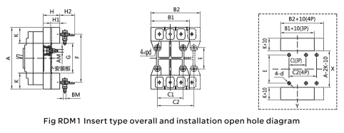
RDM1 Plug-in type overall and installation hole-opening dimension, see Fig 10, Fig 11 and Table 5

RDM1-80~630 Plug-in type circuit breaker overall dimension and installation board hole-opening dimension
| Suited MCCB(Table 5) |
Dimension code. | |||||||||||||||
| A | B1 | B2 | C1 | C2 | E | F | G | K | M | N | H | H1 | AM | BM | 4-d | |
| RDM1-80 | 135 | 75 | 100 | 50 | 75 | 60 | 117 | 100 | 17.5 | 16 | 9 | 27.5 | 17.5 | M5 | M5 | Φ5.5 |
| RDM1-125 | 168 | 91 | 125 | 60 | 90 | 56 | 132 | 92 | 38 | 32.5 | 18 | 48 | 32.5 | M6 | M8 | Φ6.5 |
| RDM1-250 | 186 | 107 | 145 | 70 | 105 | 54 | 144 | 94 | 45.5 | 34 | 15 | 49.5 | 33.5 | M6 | M8 | Φ6.5 |
| RDM1-400 | 280 | 149 | 200 | 60 | 108 | 129 | 224 | 170 | 55 | 44 | 23.5 | 59.5 | 40 | M8 | M12 | Φ8.5 |
| RDM1-630 | 300 | 182 | 242 | 100 | 158 | 123 | 234 | 170 | 65 | 50 | 30.5 | 60 | 40 | M8 | M12 | Φ8.5 |
| RDM1-800 | 305 | 210 | 280 | 90 | 162 | 146 | 242 | 181 | 62 | - | - | 87 | 60 | M10 | M14 | Φ11 |


RDM1 circuit breaker's height after installing motor operating mechanism, see Table 6
| Height/Model No.(Table 6) | RDM1-80L | RDM1-80M | RDM1-125L | RDM1-125M RDM1-125H |
RDM1-250L | RDM1-250M RDM1-250H |
| AC | 155 | 164 | 152 | 170 | 182 | 199 |
| DC | 160 | 171 | 153 | 171 | 177 | 194 |
| Height/Model No. | RDM1-400L,M,H | RDM1-630L | RDM1-630M RDM1-630H |
RDM1-800M RDM1-800H |
| DC | 246 | 262 | 262 | 252 |
Main technical parameter
4.1 Main technical parameter see Table 3
| Model No. | Frame size rated current Inm A | Rated current In (A) | Rated working voltage Ue (V) | Poles | Rated short-circuit crcuit Breaker (kA) | ||||
| Icu/ cosφ | Ics/ cos Φ | ||||||||
| 400V | 690V | 400V | 690V | ||||||
| RDM1-63L | 63 | (6), 10, 16, 20, 25, 32, 40, 50, 63 | 400 | 3 | 25 | - | 12.5 | - | ≤50 |
| RDM1-63M | 400 | 3, 4 | 50 | - | 25 | - | |||
| RDM1-63H | 400 | 3 | 50 | - | 25 | - | |||
| RDM1-125L | 125 | (10), 16, 20, 25, 32, 40, 50, 63, 80, 100, 125 | 400 | 2, 3, 4 | 35 | - | 25 | - | ≤50 |
| RDM1-125M | 400/690 | 2, 3, 4 | 50 | 10 | 35 | 5 | |||
| RDM1-125H | 400/690 | 3, 4 | 85 | 20 | 50 | 10 | |||
| RDM1-250L | 250 | 100, 125, 160, 180, 200, 225, 250 | 400 | 2, 3, 4 | 35 | - | 25 | - | ≤50 |
| RDM1-250M | 400/690 | 2, 3, 4 | 50 | 10 | 35 | 5 | |||
| RDM1-250H | 400/690 | 3, 4 | 85 | 10 | 50 | 5 | |||
| RDM1-400C | 400 | 225, 250, 315, 350, 400 | 400 | 3 | 50 | - | 35 | - | ≤100 |
| RDM1-400L | 400/690 | 3, 4 | 50 | 10 | 35 | 5 | |||
| RDM1-400M | 400/690 | 3, 4 | 65 | 10 | 42 | 5 | |||
| RDM1-400H | 400/690 | 3, 4 | 100 | 10 | 65 | 5 | |||
| RDM1-630L | 630 | 400, 500, 630 | 400 | 3, 4 | 50 | - | 25 | - | ≤100 |
| RDM1-630M | 400/690 | 3, 4 | 65 | 10 | 32.5 | 5 | |||
| RDM1-630H | 400 | 3, 4 | 100 | - | 60 | - | |||
| RDM1-800M | 800 | 630, 700, 800 | 4400/690 | 3, 4 | 75 | 20 | 50 | 10 | ≤100 |
| RDM1-800H | 400 | 3, 4 | 100 | - | 65 | - | |||
| RDM1-1250M | 1250 | 700, 800, 1000, 1250 | 400/690 | 3, 4 | 65 | 20 | 35 | 10 | ≤100 |
4.2 Overload current release consists of Thermal relay release with inverse time characteristic and Instantaneous release (electromagnetic).
| Distribution circuit breaker | Motor-protection circuit breaker | ||||||
| Rated current ln (A) | Thermal relay release | Electromagnetic release operational current (A) | Rated current ln (A) | Thermal relay release | Electromagnetic release operational current (A) | ||
| 1.05In Conventional non tripping time H (cold state) | 1.30In Conventional tripping time H (heat state) | 1.0In Conventional non tripping time H (cold state) | 1.2In Conventional tripping time H (heat state) | ||||
| 10≤ln≤63 | 1 | 1 | 10ln±20% | 10≤ln≤630 | 2 | 2 | 12ln±20% |
| 63<ln≤100 | 2 | 2 | |||||
| 100<ln≤800 | 2 | 2 | 5ln±20%, 10ln±20% | ||||
Circuit breaker accessory
5.1 Internal accessory
5.1.1 Shunt release
Connection diagram, see Fig 1 an Fig 2.
Rated voltage of control power supply: AC 50/60Hz, 230V, 400V; DC24V, circuit breaker can operate reliably under 85% to 110% of the rated control power supply voltage.
5.12 Under-voltage release
When the voltage is below 35% of the rated control power voltage, this release can prevent circuit breaker against closing. Connnection diagram, see Fig 3.
When the voltage decrease to the range of 70% to 35% of rated control power voltage, the under-voltage release would trip.
When the voltage is in the range of 85% to 110% of the rated control power voltage, this release can ensure the circuit dosing reliably.
Notice: The circuit breaker with under-voltage release could trip and close, only supplied the circuit breaker with rated voltage.
5.13 Auxiliary contact
circuit breaker has two sets contact,each set is not open on electric, the auxiliary contact details, see Table 5.
5.14 Alarm contact
Rated operational voltage’s parameter, see Table 5.
| Type | Frame size rated current Inm A | AC-15 | DC-13 | ||||
| Conventional heating current A | Rated operational voltage V | Ratwd frequency Hz | Rated current A | Rated operational voltage V | Rated current A | ||
| Auxiliary contact | lnm≤250 | 3 | 400 | 50 | 0.3 | 230 | 0.15 |
| Inm≥2400 | 3 | 0.4 | 0.15 | ||||
| Alarm contact | 63≤lnm≤800 | 3 | 0.3 | 0.15 | |||
5.15 Special circuit breaker accessories of Pre-paid meter
Shunt release of Pre-paid Meter rated operational voltage is AC230V 50Hz, Operate in the range of 65% to 110% Ue,when the Ctrl point is open, circuit breaker will be break after 0.5s to 2s deley. See Diagram:
5.16 Over-voltage circuit breaker
Over-voltage circuit breaker should be tripping under following conditions:
a) When the rated operational voltage(phase voltage)Ue lower than 262V
b) When the neutral line of three phases and four wires is breaking
c) When the neutral line misconnecting phase lines,
5.2 circuit breaker extranal accessory
5.21 Electric operation mechanism structure see Table 6
| Model | RDM 1-63, 100, 2 50 | RDM 1-400,630,800 | |||||
| Type | |||||||
| Structure | Electromagnetism | Motor | |||||
| Specification | 50Hz, 230V, 400V | ||||||
5.22 Manual operating mechanism should be installed after drilling the hole according to the diagram.
Rotary handle “OFF” indicated to horizontal position, keep the handle position, and try to operating the handle, the rotation should flexible, and the breaker should be open when the handle at horizontal position; and breaker should be closed when the handle at vertical position.
| Model No. | RDM1-63 | RDM1-100 | RDM1-250 | RDM 1-400 | RDM 1-630 | RDM 1-800 | ||
| Installation dimension | 50 | 52 | 54 | 97 | 97 | 90 | ||
| Y value of the operating handle relative to the breaker Center | 0 | 0 | 0 | 0 | 0 | 0 | ||
Overall and mounting Dimensions (mm)
5.23 Installation dimension of Mechanical interlock of two circuit breakers, see Table 6 Fig 6 and Table 8.
| Model No. | A | B | W | C | L | A | Φd |
| RDM 1-63 | 25 | 117 | 105 | 35 | 22 | 117 | 3.5 |
| RDM1-125 | 30 | 129 | 120 | 46 | 22 | 140 | 4.5 |
| RDM1-250 | 35 | 126 | 138 | 46 | 22 | 132 | 5.5 |
| RDM1-400L, M, H | 44 | 194 | 178.5 | 56 | 28 | 188 | 7 |
| RDM 1-800 | 44 | 215 | 176 | 56 | 28 | 188 | 5.5 |
| RDM 1-630 | 58 | 200 | 230 | 56 | 28 | 240 | 7 |
| RDM1-400C | 70 | 243 | 250 | 56 | 28 | 252 | 5.5 |
| Model No. | Front connection overall | Installation dimension | ||||||||||||||||||||
| W | L | H | H1 | H2 | H3 | W1 | L1 | L2 | W2 | K | N | M | X | Y | A | B | Φd | |||||
| 3P | 4P | 3P | 4P | 3P | 4P | 3P | 4P | |||||||||||||||
| RDM1-63L | 76 | - | 135 | 73 | 90.5 | 20 | 6.5 | 25 | 170 | 117 | 14 | 86.5 | 42.5 | 35 | - | 25 | 0 | 69 | - | 25 | 117 | 4 |
| RDM1-63M RDM1-63H | 76 | 102 | 135 | 82 | 98.5 | 28 | 6.5 | 25 | 170 | 117 | 14 | 86.5 | 41.5 | 35 | 26.5 | 25 | 23 | 69 | 49 | 25 | 117 | 4 |
| RDM1-125L | 92 | 122 | 150 | 68 | 86 | 24 | 7.5 | 30 | 200 | 132 | 17 | 89 | 43 | 32 | 27 | 27 | 23 | 67 | 51 | 30 | 129 | 4 |
| RDM1-125M | 92 | 122 | 150 | 86 | 104 | 24 | 7.5 | 30 | 200 | 132 | 17 | 89 | 43 | 32 | 27 | 27 | 23 | 67 | 51 | 30 | 129 | 4 |
| RDM1-125H | ||||||||||||||||||||||
| RDM1-250L | 107 | 142 | 165 | 86 | 110 | 24 | 6 | 35 | 230 | 144 | 24 | 98 | 51 | 39 | 27 | 27 | 23 | 80 | 54 | 35 | 126 | 5 |
| RDM1-250M | 107 | 142 | 165 | 103 | 127 | 24 | 6 | 35 | 230 | 144 | 24 | 102 | 51 | 39 | 27 | 27 | 23 | 80 | 54 | 35 | 126 | 5 |
| RDM1-250H | ||||||||||||||||||||||
| RDM1-400C | 140 | - | 257 | 100 | 146 | 36.5 | 7.5 | 44 | 361.5 | 225 | - | 128 | 50.5 | 20 | - | 53 | - | 90 | - | 44 | 215 | 6.5 |
| RDM1-400L | 150 | 198 | 257 | 107 | 155 | 38 | 5 | 48 | 357 | 224 | 31 | 128 | 64.5 | 48 | 48 | 66 | 66 | 90 | 90 | 44 | 194 | 7 |
| RDM1-400M | 150 | 198 | 257 | 107 | 155 | 38 | 5 | 48 | 357 | 224 | 31 | 128 | 64.5 | 48 | 48 | 66 | 66 | 90 | 90 | 44 | 194 | 7 |
| RDM1-400H | ||||||||||||||||||||||
| RDM1-630L | 182 | 240 | 270 | 112 | 160 | 45 | 3.5 | 58 | 370 | 234 | 41 | 135 | 67.5 | 45 | 45 | 66 | 66 | 90 | 90 | 58 | 200 | 7 |
| RDM1-630M RDM1-630H | 182 | 240 | 270 | 114 | 160 | 43 | 3.5 | 58 | 370 | 234 | 41 | 138 | 69 | 45 | 42.5 | 69 | 67 | 96 | 90 | 58 | 200 | 7 |
| RDM1-800M RDM1-800H | 210 | 280 | 280 | 117 | 160 | 42 | 5 | 70 | 380 | 243 | 44 | 136 | 65.5 | 48 | 48 | 67 | 67 | 82 | 82 | 70 | 243 | 7.5 |
6.2 Back connection overall dimension, see Fig 8 and Table 10.
6.3 Back connection installation open hole dimension, see Table 9
| Model No. | Dimension code. | |||||||||
| H3 | H4 | D | W | L2 | Φd2 | A | B | C | Φd1 | |
| RDM 1-63 | 28 | 46 | M5 | 25 | 117 | 8 | 25 | 117 | 50 | 5.5 |
| RDM1-125 | 64 | 100 | M8 | 30 | 132 | 24 | 30 | 129 | 60 | 5.5 |
| RDM1-250 | 70 | 100 | MIO | 35 | 144 | 26 | 35 | 126 | 70 | 5.5 |
| RDM 1-400 | 71 | 105.5 | Φ12 | 48 | 224 | 32 | 44 | 194 | 94 | 7 |
| RDM1-400C | 71 | 105.5 | Φ16 | 44 | 225 | 32 | 44 | 215 | - | 8.5 |
| RDM 1-630 | 46 | 105 | Φ16 | 58 | 234 | 37 | 58 | 200 | 116 | 7 |
| RDM 1-800 | 105 | 105 | 70 | 243 | 48 | 70 | 243 | 70 | 7.5 | |
6.4 RDM1 Insert type’s overall and installation open hole dimension, see Fig 10, Fig 11 and Table 11
| Model No. | Dimension code. | ||||||||||||||
| A | B1 | B2 | C1 | C2 | E | F | G | K | H | H1 | H2 | AM | BM | 4-d | |
| RDM 1-63 | 135 | 75 | 100 | 50 | 75 | 60 | 1 17 | 100 | 17.5 | 27.5 | 18 | 16 | M5 | M5 | Φ5.5 |
| RDM1-125 | 168 | 91 | 125 | 60 | 90 | 56 | 132 | 92 | 38 | 50 | 33 | 28 | M6 | M8 | Φ6.5 |
| RDM 1-250 | 186 | 107 | 145 | 70 | 105 | 54 | 145 | 94 | 46 | 50 | 33 | 37 | M6 | M8 | Φ6.5 |
| RDM 1-400 | 280 | 149 | 200 | 60 | 108 | 129 | 224 | 170 | 55 | 60 | 38 | 46 | M8 | M12 | Φ8.5 |
| RDM 1-630 | 280 | 144 | 88 | - | 143 | 224 | 180 | 50 | 60 | 38 | 48 | M8 | M12 | Φ9 | |
| RDM 1-800 | 300 | 182 | 242 | 100 | 158 | 123 | 234 | 170 | 65 | 60 | 39 | 50 | M8 | M12 | Φ8.5 |
| RDM1-400C | 305 | 210 | 280 | 90 | 162 | 146 | 242 | 181 | 62 | 87 | 60 | 22 | M10 | M14 | Φ11 |
6.5 RDM1 circuit breaker’s height after installing motop operating mechanism, see Table 12.
| Model No. | RDM1-65L | RDM1-63M RDM1-63H |
RDM1-100L | RDM1-100M RDM1-100H |
RDM 1-255L | RDM1-25OM RDM1-25OH |
| Height | ||||||
| AC | 155 | 164 | 152 | 170 | 182 | 199 |
| DC | 160 | 171 | 153 | 171 | 177 | 194 |
| Modd No. | RDM 1-400C | RDM1-400L. M. H | RDM1-63OL | RDM1-630M RDM1-630H |
RDM1-800M RDM1-800H |
| Height | |||||
| AC | 227 | 238 | 246 | 246 | 247 |
| DC | 160 | 255 | 262 | 262 | 261 |