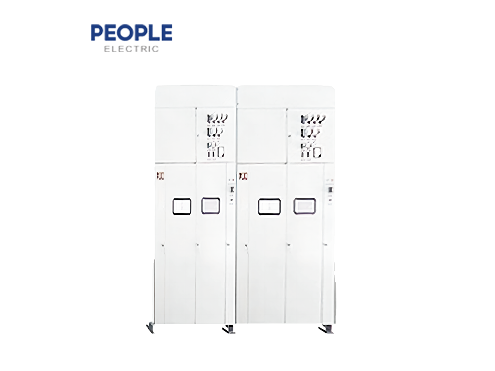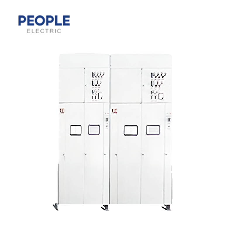
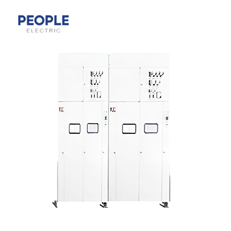
JYN1-35(F)AC metal sealed and movable switch board (in the following we call switch board ) is a type of metal sealed switching equipment for interior device using three phases and 50hz frequency AC it can be used in power plant as well as on distribution equipment complex of single bus or single bus segment whose system rated voltage is 35kv, the maximal rated current is 1000A and the highest voltage does not exceed 40.5kv in transformer room ,this type of switchboard has "five prevention" function :breaker for preventing operation by mistake preventing lord’s pushing or pulling lorry ,preventing attachment to earth with electrical preventing feeding earth connection and preventing entering electric gap by mistake.
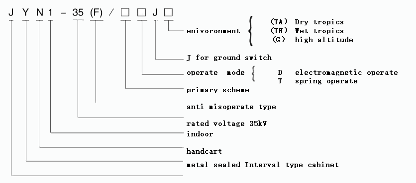
Model No.
Technique data
The primary element assembled on the switch board includes lack oil circuit breaker or vacuum breakerfunction mechanism current mutual inductor ,voltage mutual inductor fuse ,lightning arester ,electric powertransformer and so on ,on the condition that the equipment has ,these elements should have their owntechnique characters.
4.1 Switchboard technique parameter shows on
| code | Item | Unit | data | |||||||||||
| 1 | rated voltage | KV | 35 | |||||||||||
| 2 | max operate voltage | KV | 40.5 | |||||||||||
| 3 | max rated current | A | 1000 | |||||||||||
| 4 | rated break current | KA | 16/20/25/31.5 | |||||||||||
| 5 | rated closing current (peak) | KA | 40/50/63/80 | |||||||||||
| 6 | Ultimate breaking and closing current (peak) | KA | 40/50/63/80 | |||||||||||
| 7 | 4s thermal stable current(effect value) | KA | 16/20/25/31.5 | |||||||||||
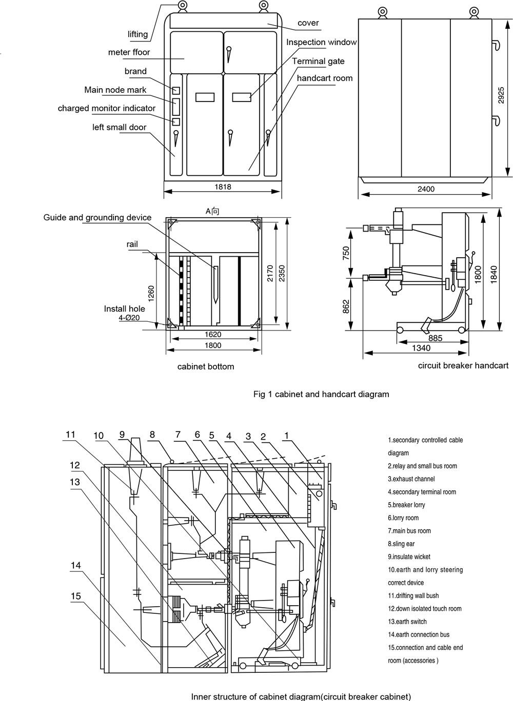
| 8 | shape(long x width x height) | KA | 1818(mm)x2400(mm)x2925(mm) | |||||||||||
| 9 | weight(oil breaker cabinet) | mm | 1800 (including oil handcart weights 620) | |||||||||||
| 10 | dyamic loadweight | Upper | kg | about 500 | ||||||||||
| lower | kg | about 500 | ||||||||||||
| 11 | Protect level | kg | IP2X | |||||||||||
4.2 Lack oil circuit breaker technique data shows on
| code | Item | Unit | data | |||||||||||
| 1 | rated voltage | KV | 35 | |||||||||||
| 2 | Max operate voltage | KV | 40.5 | |||||||||||
| 3 | rated current | KA | 1250 | |||||||||||
| 4 | rated breaking current | KA | 16/20 | |||||||||||
| 5 | rated closing current(peak) | KA | 20/50 | |||||||||||
| 6 | ultimate closing and breaking current(peak) | KA | 20/50 | |||||||||||
| 7 | 4s thermal stable current(effect value) | KA | 16/20 | |||||||||||
| 8 | Inherent switching time equip( CD10、CT10 ) | s | 0.06 | |||||||||||
| 9 | closing time equip ( CD10、CT10) | s | 0.25 0.2 | |||||||||||
| 10 | operate circulation | breaking – 0.3s – closing and breaking -180s – closing and breaking | ||||||||||||
| 4.3 CT10type spring operation mechanism main parameter | ||||||||||||||
| Stock energy motor type:HDZ1-6. | ||||||||||||||
| Stock energy motor electric power : not more than 600 w | ||||||||||||||
| Rated voltage stock energy time under rated voltage does not exceed 8 s . | ||||||||||||||
| (manipulative matrix does not exceed 7kg .m in the case of stocking energy by hand ). | ||||||||||||||
| Spring operation mechanism’s unlocking device category : divided activated undocking device | ||||||||||||||
| (code 4),instantaneously over current undocking(code 1). | ||||||||||||||
| Instantaneously over current undocking device rated current : 5A | ||||||||||||||
| Undocking device composition . | ||||||||||||||
| Please negotiate with manufacture if you need other composition or lose voltage undocking device. |
4.4 Dividable activated undocking device and brake shut electromagnet data shows on
| type | shunt release | closing electromagnet | ||||||||||||
| parameter | ||||||||||||||
| voltage type | AC | DC | AC | DC | ||||||||||
| rated voltage(V) | 110 | 220 | 380 | 48 | 110 | 220 | 110 | 220 | 380 | 48 | 110 | 220 | ||
| rated current | iron core start | 7 | 4 | 2.4 | 4.44 | 1.8 | 1.23 | 18 | 9.0 | 5 | 32 | 15.7 | 7.2 | |
| iron core attract | 4.6 | 2.5 | 1.4 | 14 | 7.1 | 3.6 | ||||||||
| rated power | iron core start | 770 | 880 | 912 | 231.2 | 198.3 | 248.2 | 1980 | 1980 | 1900 | 1536 | 1727 | 1584 | |
| iron core attract | 506 | 550 | 532 | 1540 | 1562 | 1368 | ||||||||
| active voltage range | 65~120%rated voltage | 85~110%rated voltage | ||||||||||||
4.5 CD type spring operation mechanism technique data shows on
| Item | closing coil | breaking coil | ||||||||||||
| rated voltage(V) | DC110 | DC220 | DC24 | DC48 | DC110 | DC220 | ||||||||
| active current(A) | 229 | 111 | 22.6 | 11.3 | 5 | 2.5 | ||||||||
Note: brake shut current refers to calculated count, real current is less than the calculated count
4.6 LCZ-35 current mutual inductor technique data shows on table 5,6 and diagram1
| Level combination | rated primary current(A) | rated secondary current(A) |
class | rated secondary load(VA) |
10% multiple no less than |
|||||||||
| 0.5/3 | 0.5/0.5 | 20~100 | 5 | 0.5 | 50 | |||||||||
| 0.5/B | 3/3. | 20~800 | 3 | 50 | 10 | |||||||||
| 3/B | B/B | 1000 | B | 20 | 27 | |||||||||
| B | 20 | 35 | ||||||||||||
| rated primary curent(A) | rated thermal stablecurrent(A) | rated dynamic stable current(A) |
rated primary current(A) | rated thermal stable current (A) | rated dynamic stable current(A) | |||||||||
| 20 | 1.3 | 4.2 | 200 | 13 | 42.2 | |||||||||
| 30 | 2 | 6.4 | 300 | 19.5 | 63.6 | |||||||||
| 40 | 2.6 | 8.5 | 400 | 26 | 84.9 | |||||||||
| 50 | 3.3 | 10.6 | 600 | 39 | 127.3 | |||||||||
| 75 | 4.9 | 16 | 800 | 52 | 112 | |||||||||
| 100 | 6.5 | 21.2 | 1000 | 65 | 141.4 | |||||||||
| 150 | 9.8 | 31.8 | ||||||||||||
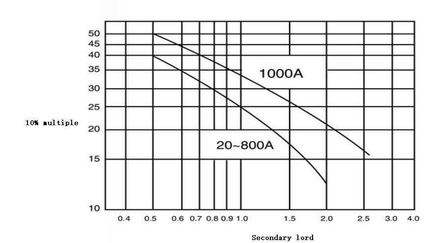
Diagram 1 LCZ-35 current mutual inductor grade B 10% multiple curve
4.7 Voltage mutual inductor technique data
| Model No. | rated voltage(V) | rated capacity(VA) | Max capacity(VA) | |||||||||||
| primary coil AX |
basic AX secondary coil aX |
auxiliary secondary coil aDXD rated capacity(VA) 0 |
0.5 class | 1 class | 3 class | |||||||||
| JDJ2-35 | 35000 | 100 | - | 150 | 250 | 500 | 1000 | |||||||
| JDJJ2-35 | 100/ .3 | 100/3 | 150 | 250 | 500 | 1000 | ||||||||
4.8 FZ-35 type lightning arrester technique data
| Rated voltage (effective value)kV |
Arc-extinction voltage (effective value) kV |
power frequencydischarge voltage(effective value)kV | impulse dischargevoltage pre-discharge time15~20ms(peak)kV | residual voltage(10/20ms)peak kV | ||||||||||
| no less than | no less than | 5kA | 10kA | |||||||||||
| 35 | 41 | 82 | 98 | no more than 134 | no more than 134 | no more than 148 | ||||||||
4.9 FYZ1-35 Zinc oxide lightning arrester technique data
| Ratedvoltage(effective) kV |
arrestershort-timeMax operatevoltagekV (effective) |
criticalpoint ofactionvoltage(lower limit)kv(peak) | impulse voltageresidual voltage(wave form 8/20micro-seconds)(no more than)kV | breaking and makingcapacity(no less than 20) | residual voltage(10/20ms)peak kV | |||||||||
| 2ms square waveno less than(A) | 18/40mS impulse current(no less than)kA (peak value) |
impulseprotect ratioU5kA |
operate protect ratioU300A |
|||||||||||
| 35 | 41 | 59 | 126 | 300 | 10 | 2.1 | 1.8 | |||||||
4.10 RN 2 type high voltage rated current fuse technique data
| rated voltage kv |
rated current kV |
phase-loss capacity (3-phase)MVA MVA |
Max breaking current kA |
Max current(peak) of ultimate short -circuit current breaking(A) |
fuse resistance | |||||||||
| 35 | 0.5 | 1000 | 17 | 700 | 315 | |||||||||
4.11 Rw10-35/3 type limited current fuse technique data
| model No. | rated voltage kV | rated current kA | phase-loss capacity (3-phase)MVA |
Max breaking current kA | ||||||||||
| RW10-35/3 | 35 | 3 | 1000 | 16.5 | ||||||||||
4.12 Sj-5/0.4/0.23 type distribution transformer technique data
| rated capacity kVA | rated voltage kV | rated current A | loss A | |||||||||||
| hign-voltage | low-voltage | hign-voltage | low-voltage | hign-voltage | low-voltage | |||||||||
| 50 | 35 | 0.4 | 0.825 | 72.2 | 490 | 1325 | ||||||||
| resistance voltage % | without load current % | connection group | weight kg | |||||||||||
| total | oil weight | |||||||||||||
| 6.5 | 9 | Y/Y0-12 | 880 | 340 | ||||||||||
4.13 ZN23-35 inner high voitage vacuum breaker main technique parameter
| code | Item | Unit | data | |||||||||||
| 1 | rated voltage | KV | 35 | |||||||||||
| 2 | Max operate voltage | KV | 40.5 | |||||||||||
| 3 | rated insulation level | KV | power frequency 95 one min;thunder impulse(peak) 185 | |||||||||||
| 4 | rated current kV |
A | 1600 | |||||||||||
| 5 | rated short-circuit breaking current | KA | 25/31.5 | |||||||||||
| 6 | rated breaking current break number of times | time | 20 | |||||||||||
| 7 | rated short-circuit closing current(peak) | KA | 63/80 | |||||||||||
| 8 | rated short-circuit continuous time | S | 4 | |||||||||||
| 9 | rated operate sequence | break -0.3 – cose and break 180s – close and break | ||||||||||||
| 10 | closing time | S | ≤0.2 | |||||||||||