1.Combine flexibility and economic efficiency
2.Quality parts,durability
3.Modular design,safe & reliable
4.Overload,under-voltage,short-circuit and single-phase grounding protection
5.Standard:IEC60947-2
6.Inteligent controller protection characteristics has inverse time limit and fixed time limit, when the faut current exceeds the seting value of inverse time limit
| Model No. | RDW5-1600 | RDW5-2000 | RDW5-2500 | RDW1-3200 | RDW5-4000 | RDW5-6300 | ||||||||
| Rated current (A) | 200,400,630,800, 1000,1250,1600 |
630,800,1000, 1250,1600,2000 |
1000,1250,1600, 2000,2500 |
2000,2500,2900,3200 | 2000,2500,2900, 3200,3600,4000 |
4000,5000,6300 | ||||||||
| Neutral rated current ln (A) | 100%ln | 100%ln | 100%ln | 100%ln | 100%ln | 100%ln | ||||||||
| Rated operating voltage (V) | AC 400/690 | |||||||||||||
| Frequency (Hz) | 50/60Hz | |||||||||||||
| Number of poles | 3P/4P | |||||||||||||
| Rated impulse withstand voltage Uimp (Kv) | AC 12 | |||||||||||||
| Rated isolation voltage Ui (V) | AC 1000 | |||||||||||||
| Power frequency withstand voltage (V) 1min | 3500 (Main circuit) | |||||||||||||
| Breaking capacity grade | S | H | S | H | S | H | S | H | S | H | S | H | ||
| Rated ultimate short circuit breaking capacity (Icu) kA | AC400V | 50 | 65 | 80 | 80 | 80 | 100 | 80 | 100 | 100 | 100 | 120 | 135 | |
| AC690V | 36 | 50 | 50 | 65 | 65 | 70 | 65 | 70 | 65 | 85 | 85 | 120 | ||
| Rated operating short circuit breaking (Ics) kA | AC400V | 50 | 55 | 80 | 80 | 80 | 85 | 80 | 85 | 85 | 100 | 100 | 135 | |
| AC690V | 36 | 42 | 50 | 65 | 65 | 70 | 65 | 70 | 65 | 85 | 75 | 120 | ||
| Rated withstand current for short-time(Icw) kA |
AC400V | 42 | 50 | 65 | 65 | 80 | 85 | 80 | 85 | 85 | 100 | 85 | 135 | |
| AC690V | 36 | 42 | 40 | 55 | 65 | 65 | 65 | 70 | 65 | 85 | 75 | 120 | ||
| Using type | B type | |||||||||||||
| Breaking time(without any auxiliary delay) | 25-30ms | |||||||||||||
| Closing time | ≤70ms | |||||||||||||
| Using life | Electrical life | 5600 | 5600 | 3500 | 3500 | 4200 | 1000 | |||||||
| Mechanical life(without maintenance) | 10000 | 10000 | 7000 | 7000 | 7000 | 6500 | ||||||||
| Mechanical life(maintenance) | 20000 | 20000 | 14000 | 14000 | 14000 | 13000 | ||||||||
| Wire incoming pattern | Wire to enter from the upper or lower port | |||||||||||||
| Arc distance(mm) | 0 | |||||||||||||
| Installation method | Fixed type or draw-out type | |||||||||||||
Remote operation

RDW5-1600
Closing electromagnetic coil
RDW5-2500~6300
Closing electromagnetic coil
● Closing electromagnetic coil
| Operating voltage Us | AC230V | AC400V | DC220V | DC110V |
| Action voltage range | (85~110)%Us | |||
| Startup current | 1.3A | 0.7A | 1.3A | 2.5A |
| Pull-in time | ≤60ms | |||
Note: When the circuit breaker completes the energy storage operation and at the normal opening status, the circuit breaker can be fast closed by using the closing electromagnetic coil remotely control
RDW5-1600
Shunt release
RDW5-2500~6300
Shunt release
● Shunt release
| Operating voltage Us | AC230V | AC400V | DC220V | DC110V |
| Action voltage range | (70~110)%Us | |||
| Action voltage range | 1.3A | 0.7A | 1.3A | 2.5A |
| Pull-in time | ≤30ms | |||
Note: When the circuit breaker is at the closing status, the circuit breaker can be fact opened by the shunt release remotely control

RDW5-1600
Undervoltage release
RDW5-2500~6300
Undervoltage release
● Undervoltage release
| Operating voltage Us | AC230V | AC400V |
| Action voltage range | (35~70)%Ue | |
| Reliably closing voltage range | (85~110)%Ue | |
| Cannot closing voltage range | ≤35%Ue | |
| Power consumption | 20VA | |
| RDW5-1600 Tripping time | Instantaneous,1s,3s,5s,10s,15s,20s | |
| Above RDW5-2500 tripping time | Instantaneous,0.5s,1s, 3s, 5s | |
Note: 1. When the undervoltage tripping device is not powered, the circuit breaker cannot be closed; 2. Within 1/2 delay tripping time, when the working voltage is restored to more than 85%Ue, the circuit breaker is not opened; 3. In lightning-prone areas and power grids with unstable power supply voltage, it is recommended to use the undervoltage tripping device with delay to prevent the circuit breaker disconnection due to short-term voltage reduction.

RDW5-1600
Energy storage motor
RDW5-2500~6300
Energy storage motor
● Energy storage motor
| Operating voltage Us | AC230V | AC400V | DC230V | DC110V |
| Operating voltage range | (85~110)%Ue | |||
| Energy storage time | 5s | |||
| RDW5-1600 Power consumption | 70VA | 75W | ||
| RDW5-2500 Power consumption | 110VA | 110W | ||
| Above RDW5-4000 | 150VA | 150W | ||
Remark: 1. Realizing the electric energy storage of the circuit breaker and the automatic energy storage operation after the circuit breaker is closed, so that the circuit breaker can be immediately closed after the circuit breaker is broken;
2. Manual energy storage operation can also be carried out during circuit breaker maintenance.
Lock and interlock

Drawer operation padlock
Key lock
● Drawer operation padlock
1. When the main body of the drawer type circuit breaker is at the position of "separate", pull out the card board and lock it by the padlock, the main body cannot be shaken to the “testing" or "connecting" position after locking.(The padlock is provided by the user)
● Key lock
1. The key lock can lock the circuit breaker in the disconnected position. The circuit breaker can be closed only if the lock is opened by the key and the key is not pulled out
2. There are three kinds of common key locks: one lock and one key; two locks and one key; and three locks and two keys.
Note: Two locks and three locks are used in the power distribution system with two incoming lines and one connection

Position lock interlock
Drawer position interlocking mechanism
Mechanical interlock
● Position lock interlock
1. When the drawer circuit breaker body is in the “test" or “connection" position,the cabinet door is forbidden to open. When the circuit breaker body is in the“separate" position, the cabinet door is allowed to open.
● Drawer position interlocking mechanism
1. In the drawer breaker, the locking device of the “connection", “test" and“separate" positions of the breaker, the three positions of the breaker are displayed through the indicator window, pull in and pull out the handle is locked in the exact position, and can be unlocked by the reset button.
● Mechanical interlock
1. There are two kinds of interlocks: lever interlock and cable interlock
2. Using lever interlock, two or three circuit breakers can only be installed vertically, using cable interlock, and circuit breakers can be installed horizontallyand vertically
Indicate contact

RDW5-1600
Auxiliary switch
RDW5-2500~6300
Auxiliary switch
● Auxiliary switch
| Rated operating voltage | AC230V | AC400V | DC220V | DC110V |
| Setting thermal current | 6A | |||
| Rated control capacity | 300VA | 60W | ||
Note:1. Default configuration: four sets of conversion contacts
2. Other type: 4N04NC,6 groups of conversion contacts, 6NO6NC

Position signal device wiring diagram
● Position signal device wiring diagram
1.Drawer type optional accessories
2. The three-position indicator contact is installed on the extracted frame t oindicate the circuit breaker in the drawer position
3. When the circuit breaker is in the connection position, see the left wiring diagram and see the figure
Controller accessories

N Pole current transformer
ZCT
Zero sequence
current transformer
Grounding currenttransformer
● N Pole current transformer
1. In the grounding mode of 3P+N, the external transformer used to measure the neutral phase current is set on the wiring bus by the user
2. Choose from three options with grounding transformer and leakage transformer
● CT1 Zero sequence current transformer
1. When the grounding protection is the residual current type, a zero-sequence current transformer should be applied. Signal sampling methods is the vector sum of each phase current, it is applicable for the protection of small current
● Grounding current transformer
1. The special external transformer used to measure the neutral phase current can protect the upper and lower grounding faults of the circuit breaker simultaneously
2. The grounding mode is the ground current return type
3. Only for R / H type controllers
4. With N phase external transformer and leakage transformer

Auxiliary power module
Relay module
● Auxiliary power module
1. Input voltage:AC230V/AC400V/DC110V/DC220V (option)
2. Auxiliary power supply module can provide power not less than 9.6W, DC24Vpower supply, can output four sets of terminals, can provide power supply for intelligent controller and relay module
3. The installation method is 35mm standard guide rail or direct installation
● Relay module
1.Input voltage: DC24V
2.Contacts capacity:AC250V 10A; DC28V 10A
3. When the load capacity of the switch of the control circuit breaker is large, it should be controlled through the relay module conversion
4.The installation method is 35mm standard guide rail or direct installation
RDW5-1600S ACB (Withdrawable type) overall and installation dimensions
● RDW5-1600S ACB (Withdrawable type) overall dimension

● RDW5-1600S ACB (Withdrawable type) installation dimension

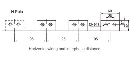
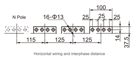
● RDW5-1600S ACB (Withdrawable type) wiring dimension

| Rated current(A) | Thickness of busbar H(mm) |
| 200、400、630 | 6 |
| 800、1000 | 10 |
| 1250、1600 | 18 |
RDW5-1600S the correspondence between the current and the busbar thickness
RDW5-1600H ACB (Withdrawable type) overall and installation dimensions
● RDW5-1600H ACB (Withdrawable type) overall dimensions

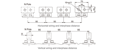
● RDW5-1600H ACB (withdrawable type) Installation size and frame hole-opening size

● RDW5-1600H ACB (withdrawable type) Installation dimension

| Rated current(A) | Thickness of busbar H(mm) |
| 200、400、630 | 5 |
| 800、1000 | 10 |
| 1250、1600 | 15 |
RDW5-1600H the correspondence between the current and the busbar thickness
RDW5-1600S ACB (Fixed type) overall and installation dimensions
● RDW5-1600S ACB (Fixed type) overall dimensions

● RDW5-1600S ACB (Fixed type) installation size and frame hole-opening size

●RDW5-1600S ACB (Fixed type) installation dimension

| Rated current(A) | Thickness of busbar H(mm) |
| 200、400、630 | 6 |
| 800、1000 | 10 |
| 1250、1600 | 18 |
RDW5-1600S the correspondence between the current and the busbar thickness
RDW5-1600H ACB (Fixed type) overall and installation dimensions
●RDW5-1600H overall dimension

●RDW5-1600H installation dimension

●RDW5-1600H installation dimension

| Rated current(A) | Thickness of busbar H(mm) |
| 200、400、630 | 5 |
| 800、1000 | 10 |
| 1250、1600 | 15 |
RDW5-1600H the correspondence between the current and the busbar thickness
RDW5-2000/2500 S/HACB (Withdrawable type) overall and installation dimensions
●RDW5-2000/2500 S/H Overall dimension

● RDW5-2000/2500 S/H installation dimension and frame hole-opening dimension

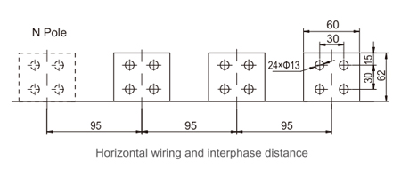
● RDW5-2000S wiring dimension

| Rated current(A) | Thickness of busbar H(mm) |
| 630、800 | 10 |
| 1000、1250、1600 | 15 |
| 2000 | 20 |
RDW5-2000S the correspondence between the current and the busbar thickness
● RDW5-2000H wiring dimension

| Rated current(A) | Thickness of busbar H(mm) |
| 630、800 | 10 |
| 1000、1250、1600 | 15 |
| 2000 | 20 |
RDW5-2000H the correspondence between the current and the busbar thickness
RDW5-2000/2500 S/H ACB(Fixed type)overall and installation dimensions
● RDW5-2000/2500 S/H overall dimensions

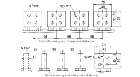
● RDW5-2000/2500 S/H installation dimension and frame hole-opening dimension

● RDW5-2000S wiring dimension

| Rated current(A) | Thickness of busbar H(mm) |
| 630、800 | 10 |
| 1000、1250、1600 | 15 |
| 2000 | 20 |
RDW5-2000S the correspondence between the current and the busbar thickness
● RDW5-2000H wiring dimension

| Rated current(A) | Thickness of busbar H(mm) |
| 630、800 | 10 |
| 1000、1250、1600 | 15 |
| 2000 | 20 |
RDW5-2000H the correspondence between the current and the busbar thickness
● RDW5-2500S wiring dimension

| Rated current(A) | Thickness of busbar H(mm) |
| 1000、1250、1600 | 15 |
| 2000、2500 | 20 |
RDW5-2500S the correspondence between the current and the busbar thickness
● RDW5-2500H Wiring dimension

| Rated current(A) | Thickness of busbar H(mm) |
| 1000、1250、1600 | 15 |
| 2000、2500 | 20 |
RDW5-2500H the correspondence between the current and the busbar thickness
RDW5-3200/4000 S/H ACB (Withdrawable type) overall and installation dimensions
● RDW5-3200/4000 S/H overall dimension

● RDW5-3200/4000 S/H installation dimension and frame hole-opening dimension

RDW5-3200/4000 S/H ACB (Withdrawable type) overall and installation dimensions
● RDW5-3200S wiring dimension

| Rated current(A) | Thickness of busbar H(mm) |
| 2000、2500 | 20 |
| 2900、3200 | 30 |
RDW5-3200S the correspondence between the current and the busbar thickness
● RDW5-3200H wiring dimension

| Rated current(A) | Thickness of busbar H(mm) |
| 2000、2500 | 25 |
| 2900、3200 | 25 |
RDW5-3200H the correspondence between the current and the busbar thickness
RDW5-3200/4000 S/H ACB (Withdrawable type)overall and installation dimensions
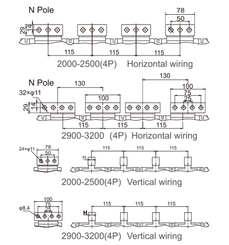
● RDW5-4000S wiring dimension


● RDW5-4000H wiring dimension

RDW5-3200/4000 S/H ACB (Fixed type) overall and installation dimensions
● RDW5-3200/4000 S/H overall dimension

● RDW5-3200/4000 S/H installation dimension and frame hole-opening dimension

RDW5-3200/4000 S/H ACB (Fixed type) overall and installation dimensions
● RDW5-3200S wiring dimension

| Rated current(A) | Thickness of busbar H(mm) |
| 2000、2500 | 20 |
| 2900、3200 | 30 |
RDW5-3200S the correspondence between the current and the busbar thickness
● RDW5-3200H wiring dimension

| Rated current(A) | Thickness of busbar H(mm) |
| 2000、2500 | 25 |
| 2900、3200 | 25 |
RDW5-3200H the correspondence between the current and the busbar thickness
● RDW5-4000S wiring dimension

| Rated current(A) | Thickness of busbar H(mm) |
| 2000、2500 | 20 |
| 2900、3200、4000 | 30 |
RDW5-4000S the correspondence between the current and the busbar thickness
● RDW5-4000H wiring dimension

| Rated current(A) | Thickness of busbar H(mm) |
| 2000、2500 | 20 |
| 2900、3200、4000 | 30 |
RDW5-4000H the correspondence between the current and the busbar thickness
RDW5-6300S ACB (Withdrawable type)overall and installation dimensions
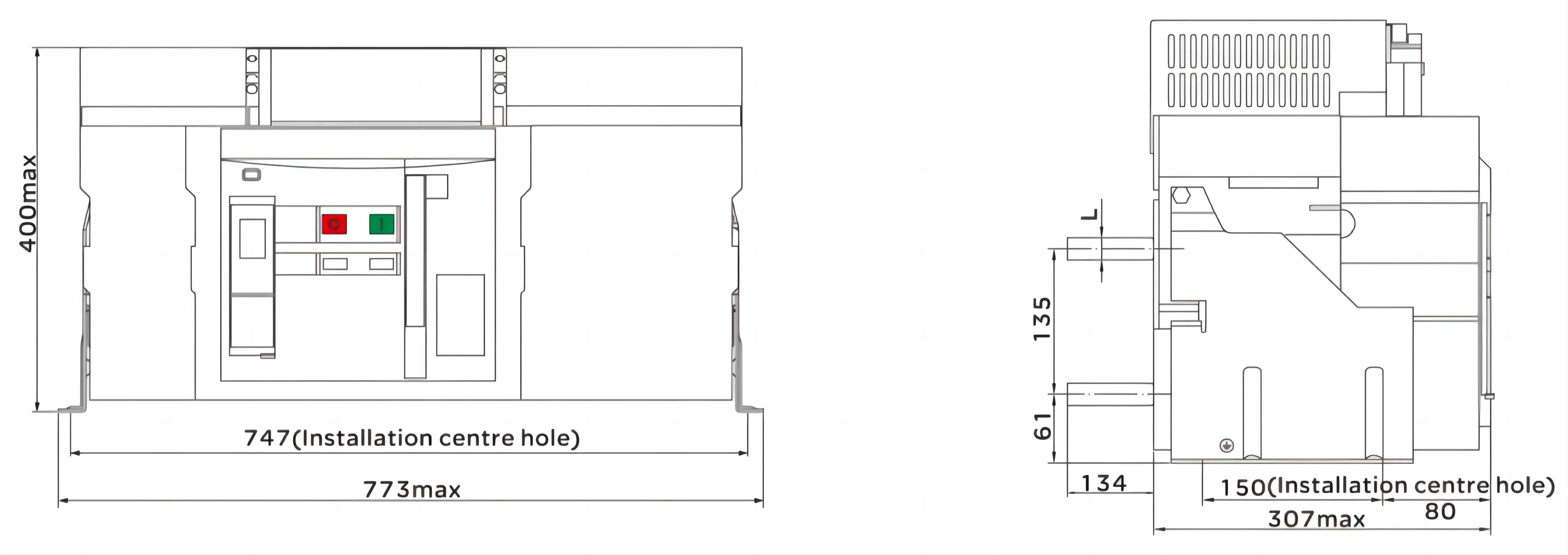
● RDW5-6300S overall dimension

● RDW5-6300S installation dimension and frame hole-opening dimension

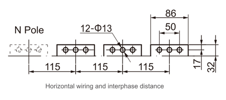
● RDW5-6300S wiring dimension

| Rated current(A) | Thickness of busbar H(mm) |
| 4000 | 20 |
| 5000、6300 | 30 |
RDW5-6300S the correspondence between the current and the busbar thickness
RDW5-6300H ACB (Withdrawable type) overall and installation dimensions
● RDW5-6300H overall dimension

● RDW5-6300H installation dimension and frame hole-opening dimension

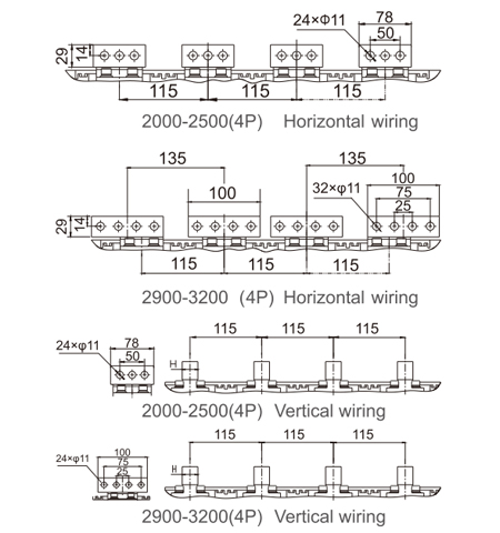
● RDW5-6300H wiring dimension

RDW5-6300H ACB(Fixed type) overall and installation dimensions
● RDW5-6300H overall dimension

● RDW5-6300H installation dimension and frame hole-opening dimension

● RDW5-6300H wiring dimension

| Rated current(A) | Thickness of busbar H(mm) |
| 4000 | 25 |
| 5000、6300 | 30 |
RDW5-6300S the correspondence between the current and the busbar thickness
| Rated current (A) | External copper bar specification W x T(mm) | Number of pieces per terminal | Sectional area of each terminal(mm²) |
| 200 | 20×5 | 1 | 100 |
| 400 | 40×5 | 1 | 200 |
| 630 | 40×5 | 2 | 400 |
| 800 | 50×5 | 2 | 500 |
| 1000 | 60×5 | 2 | 600 |
| 1250 | 80×5 | 2 | 800 |
| 1600 | 100×5 | 2 | 1000 |
| 2000 | 100×5 | 3 | 1500 |
| 2500 | 100×5 | 4 | 2000 |
| 2900 | 100×10 | 3 | 3000 |
| 3200 | 100×10 | 4 | 4000 |
| 3600 | 100×10 | 5 | 5000 |
| 4000 | 100×10 | 5 | 5000 |
| 5000 | 100×10 | 6 | 6000 |
| 6300 | 100×10 | 8 | 8000 |
| Model No | RDW5-1600 | RDW5-2500 | RDWH-3200 | RDW5-4000 | RDW5-6300 | |||||
| Rated current (A) | 200,400,630,800 1000,1250,1600 |
1000,1250,1600, 2000,2500 | 2000,2500,2900 3200,3600,4000 |
3200,3600,4000 | 400,050,006,300 | |||||
| Neutral rated current In (A) | 100%In | 100%ln | 100%In | 100%In | 50%ln | |||||
| Rated operating voltage (V) | AC400/690 | |||||||||
| Frequency (Hz) | 50/60Hz | |||||||||
| Number of poles | 3P/4P | |||||||||
| Rated impulse withstand voltage Uimp(Kv) | Ad12 | |||||||||
| Rated isolation voltage Ui(V) | AC 1000 | |||||||||
| Power frequency withstand voltage (V) 1min | 3500 (Main circuit) | |||||||||
| Rated ultimate short circuit breaking capacity (lcu) kA |
AC400V | 42 | 80 | 100 | 80 | |||||
| AC690V | - | 50 | 65 | - | ||||||
| Rated operating short circuit breaking capacity (lcs) kA |
AC400V | 32 | 65 | 80 | 65 | |||||
| AC690V | - | 50 | 65 | - | ||||||
| Rated withstand current for short- time (Icw) 1s(kA) |
AC400V | 20/30(0.5s) | 65 | 80 | 65 | |||||
| AC690V | - | 40 | 50 | - | ||||||
| Rated short circuit connection ability (Icm) kA | Electrical life | 7000 | 6500 | 3000 | 3000 | |||||
| Mechanical life | 15000 | 15000 | 10000 | 10000 | ||||||
| Using type | B type | |||||||||
| Breaking time (without any auxiliary delay) | 25-30ms | |||||||||
| Closing time | ≤70ms | |||||||||
| Operation life (times) 2500A below | 400V electrical life |
8000 | 8000 | 5000 | 1500 | |||||
| 690V electrical life |
3000 | 2500 | 2000 | 1000 | ||||||
| 1time/3min; Above 2500A 1time/6min |
Mechanical life (maintenance-free) |
15000 | 12500 | 10000 | 6500 | |||||
| Mechanical life (maintenance) |
30000 | 25000 | 20000 | 13000 | ||||||
| Wire incoming pattern | Wire to enter from the upper or lower port | |||||||||
| Arc distance (mm) | 0 | |||||||||
| Installation method | Fixed type or draw-out type | |||||||||
| Draw-out type | Fixed type | ||||||||
| Model | Poles | Width (mm) |
Height (mm) |
Depth mm) |
Weight (kg) |
Width (mm) |
Height (mm) |
Depth (mm) |
Weight (kg) |
| RDW5-1600 | 3P | 282 | 351 | 345 | 43 | 254 | 320 | 254 | 22 |
| 4P | 352 | 351 | 345 | 55 | 324 | 320 | 254 | 26.5 | |
| RDW5-2500 | 3P | 375 | 435 | 485 | 84 | 368 | 400 | 360 | 47 |
| 4P | 470 | 435 | 485 | 96 | 463 | 400 | 360 | 56 | |
| RDW5-4000 | 3P | 435 | 435 | 515 | 100 | 428 | 400 | 392 | 53 |
| 4P | 550 | 435 | 515 | 130 | 543 | 400 | 392 | 67 | |
| RDW5-6300 | 3P | 780 | 435 | 515 | 195 | 773 | 400 | 441 | 106 |
| 4P | 895 | 435 | 515 | 225 | 888 | 400 | 441 | 120 | |
| Overall dimension | Horizontal connection and overall dimension |
 |
|
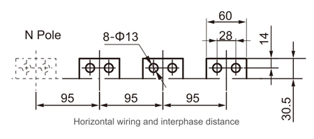
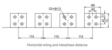
| RDW5-6300/3P Fixed type horizontal connection | Horizontal connection and phase spacing |
 |
|
| Installation dimension | The relationship with busbar thickness and current | |
 |
Rated current A | Busbar thickness mm |
| 4000 | 20 | |
| 50006300 | 30 | |
| Overall dimension | Horizontal connection and overall dimension |
 |
|
| RDW5-6300/4P Fixed type horizontal connection | Horizontal connection and phase spacing |
 |
|
| Doorframe installation dimension of RDW5-4000-6300 fixed type | Installation dimension |
 |
|
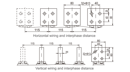
| Overall dimension | Horizontal connection and phase spacing | Installation dimension |
 |
||
| RDW5-6300/3P The vertical connection of fixed type | Vertical connection and phase spacing |
 |
|
| Overall dimension | Horizontal connection and overall dimension | Installation dimension |
 |
||
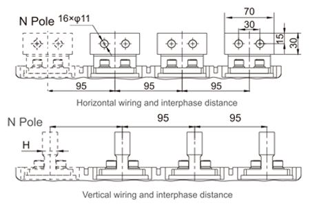
| RDW5-6300/4P The horizontal connection of fixed type | Horizontal connection and phase spacing |
 |
|
| RDW5-6300/4P The vertical connection of fixed type | Vertical connection and phase spacing |
 |
|