


1.Installation location no more than 2000m;
2.Temperature: not higher than +40℃,and no lower than -25℃, and the average temperature no higher than +35℃;
3.The relative humidity: no more than 50%,when temperature is +40℃.The product can withstand the higher humidity under lower temperature, for instance, when temperature at +20℃, the product can withstand 90% relative humidity;
4.Class of pollution:3 class;
5.Main circuit breaker installation type:Ⅲ class, Auxiliary circuit and control circuit installation type:Ⅱ class .
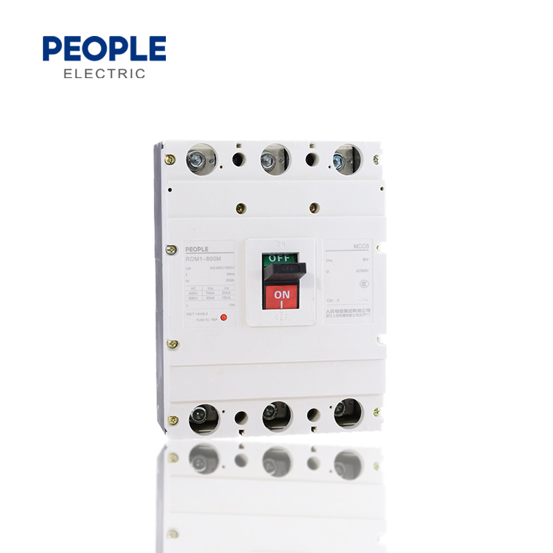
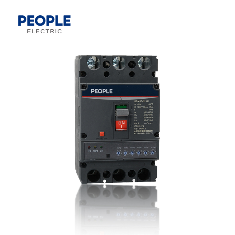
Intelligent controller is the main parts of the MCCB, it is applicable for the motor protection or the distribution protection, to realize the measurement, protection, control and communication functions are integrated,so that the line and power equipment are free from overload short circuit, grounding and other fault damages.
Using MCU micro processing controller, stable and reliable performance: this intelligent controller can supply the power, only one phase is electrified, when the current is not lower than 35% of its rated current, all can ensure the protection function is working normally.
1.Selective cooperation has three-stage protection: the circuit breaker of class B and other short circuit protection devices can selectively cooperate under short circuit conditions; the setting of overload long delay reverse time limit, short circuit delay (reverse time limit, fixed time limit), short circuit instantaneous and other protection function parameters
2.With three parameter sets of action current and action time, it can be adjusted from 4-10 stages: the user can adjust the controller according to the load current requirements, or choose to close the corresponding function
3.High current instantaneous tripping function: when the circuit breaker is closed for operation, if has the short circuit high current (≥20Inm,the circuit breaker magnetic tripping mechanism can be directly disconnected, the double protection is more reliable and safe
4.With the tripping test (test) function: input DC DC12V voltage to test the circuit breaker action characteristics
5.Fault self-diagnosis function: to protect and detect the working state and operation situation of the intelligent controller itself
6. With the forecast warming indication, overload indication: when the load current reaches or exceeds the setting value, the light guide column exports the light source
7. Magnetic flux converter double air gap technology: work more reliable and stable, prevent misoperation, reliable tripping, low power
8.High protection accuracy: overload protection, short circuit, shot delay protection action current accuracy +10%; short circuit instantaneous protection value accuracy of + 15% depends on the action current
Optional Function
1.Dual passive signal output function: signal (or alarm),AC230V ЗA
2.With fire protection shunt function: overload alarm does not trip (provide a pair of passive contacts) and provide shunt release function
3.With communication function: standard RS485, Modbus Fieldbus Agreement
| RDM5E-125 | RDM5E-250 | RDM5E-400 | RDM5E-800 | |||||
| Rated current of frame size Inm (A) | 125 | 250 | 400 | 800 | ||||
| Rated current (A) | 32, 63, 125 | 250 | 400 | 630, 800 | ||||
| Poles | 3,4 | 3,4 | 3,4 | 3,4 | ||||
| Rated frequency (Hz) | 50 | |||||||
| Rated insulation voltage Ui (V) | AC 1000 | |||||||
| Rated impulse withstand voltage Uimp (V) | 12000 | |||||||
| Rated working voltage Ue (V) | 400/690V | |||||||
| Arc distance (mm) | ≤50 | ≤50 | ≤100 | ≤100 | ||||
| Rated short circuit breaking capacity | M | H | M | H | M | H | M | H |
| Rated limit/Rated operation Icu/Ics (KA) at 400V | 35/23 | 50/35 | 35/23 | 50/35 | 50/35 | 70/50 | 50/35 | 70/50 |
| Rated limit/Rated operation Icu/Ics (KA) at 690V | 15/8 | 20/10 | 15/8 | 20/10 | 15/8 | 20/10 | 15/8 | 20/10 |
| Rated short-time withstand current Icw (KA/1s) | 1.5 | 3 | 5 | 10 | ||||
| Usage category | A | A | B | B | ||||
| Conforms to standard | IEC60947-2 | |||||||
| Using environment condition | -35~+70℃ | |||||||
| Electrical life (cycles) | 5000 | 3500 | 1500 | 500 | ||||
| Mechanical life (cycles) | 10000 | 10000 | 5000 | 3000 | ||||
| Front connection | ■ | ■ | ■ | ■ | ■ | ■ | ■ | ■ |
| Rear connection | ■ | ■ | ■ | ■ | ■ | ■ | ■ | ■ |
| Plug-in connection | ■ | ■ | ■ | ■ | ■ | ■ | ■ | ■ |
| Undervoltage release | ■ | ■ | ■ | ■ | ■ | ■ | ■ | ■ |
| Shunt release | ■ | ■ | ■ | ■ | ■ | ■ | ■ | ■ |
| Auxiliary contacts | ■ | ■ | ■ | ■ | ■ | ■ | ■ | ■ |
| Alarming contacts | ■ | ■ | ■ | ■ | ■ | ■ | ■ | ■ |
| Motor operation mechanism | ■ | ■ | ■ | ■ | ■ | ■ | ■ | ■ |
| Manual operation mechanism | ■ | ■ | ■ | ■ | ■ | ■ | ■ | ■ |
| Intelligent control module | ■ | ■ | ■ | ■ | ■ | ■ | ■ | ■ |
| Testing power module | ■ | ■ | ■ | ■ | ■ | ■ | ■ | ■ |
Specification allocation
| No. | Name | 10p accessory function | Rated power voltage (range) | Rated control signal voltage (range) |
| 1 | Four remote accessories |
Four remote communication+ Reset button+working indication |
DC24V (85%~110%) | Status signal DC24V (85%~110%)Motor operation signal DC24V |
| AC230V (85%~110%) | Status signal AC230V (85%~110%)Motor operation signal AC230 | |||
| Remark: Reset button function, pressing and holding for 5s;Communication baud rate, communication address and other parameters are restored to factory values | ||||


Rated value of auxiliary contacts and alarming contacts
| Classification | Rated current of frame size Inm (A) | Setting thermal current Ith (A) | Rated working current Ie (A) | |
| AC400V | DC200V | |||
| Auxiliary contacts | Inm≤400 | 3 | 0.3 | 0.15 |
| Inm≥400 | 3 | 0.4 | 0.15 | |
| Alarming contacts | 100≤Inm≤800 | 3 | 0.3 | 0.15 |
Rated control power voltage (Us) and rated working voltage (Ue) of control circuit release and electric operaion mechanism
| Type | Rated voltage (V) | |||
| AC50Hz | DC | |||
| Release | Shunt release | Us | 230、400 | 24 |
| Undervoltage release | Ue | 230、400 | -- | |
| Electric operation mechanism | Us | 230、400 | 110、220 | |
口External voltage of shunt release is within 70%~100% of rated control power voltage, it should reliably break the circuit breaker.
口When the power voltage reduces to the 70%~35% of the undervoltage release's rated voltage,the undervoltage release should reliably break the circuit breaker, When the power voltage is lower than 35% of the undervoltage release's rated voltage, the undervoltage release can prevent the circuit breaker closing. When the power voltage is higher than 85% of the undervoltage release's rated voltage,the undervoltage release can ensure the circuit breaker reliably close.
口When the electric operation mechanism is under the rated frequency, and the power voltage between 85%~110%,it can reliably close the circuit breaker.
Power consumption
| Model No. | Electrified current(A) | Three-phase total power loss(VA) | |
| Front and rear wiring | Plug-in type wiring | ||
| RDM5E-125 | 125 | 35 | 40 |
| RDM5E-250 | 250 | 62 | 70 |
| RDM5E-400 | 400 | 115 | 125 |
| RDM5E-800 | 800 | 262 | 294 |
Capacity reduction coefficient of ambient temperature change (all measured under the rated current of the same case frame)
| Capacity reduction / Environment temperature/ Model No. |
+40℃ | +45℃ | +50℃ | +55℃ | +60℃ | +65℃ | +70℃ |
| RDM5E-125 | 1ln | 1ln | 1ln | 0.97ln | 0.95ln | 0.92ln | 0.9ln |
| RDM5E-250 | 1ln | 1ln | 1ln | 0.96ln | 0.93ln | 0.89ln | 0.86ln |
| RDM5E-400 | 1ln | 1ln | 1ln | 0.97ln | 0.95ln | 0.92ln | 0.9ln |
| RDM5E-800 | 1ln | 1ln | 1ln | 0.96ln | 0.93ln | 0.89ln | 0.86ln |
口 RDM5E MCCB with the electric operation mechanism is connected with the upper computer (such as computer), it can realize the remote " Four remote" function through the communication interface, RS485 interface, Modbus-RTU protocol, communication baud rate 9600K.Additionally, adding the RDM5E MCCB controller (optional accessories) can be directly read and modify the parameters of the circuit breaker in the field
口 Communication interface and external module of electronic type MCCB
口 RDM5E communication MCCB has the communication interface, MODBUS communication protocol
口When the RDM5E communication MCCB is not used for the network communication but for singly use, the handheld programmer can adjust the protection characteristics of the circuit breaker through the communication interface, the RD-CD LCD display module can also be connected to the communication interface to monitor the operating current and fault information of the circuit breaker
口When RDM5E communication MCCB is used for the network, it can be directly connected to the responding field bus, Refer to the field bus with different protocol, can use RD-DP protocol conversion module, to converse the MODBUS protocol and connect to the responding field bus
口The communication network of RDM5E series communicable electronic plastic case circuit breaker can be connected with reference to the scheme in the figure below

RDM5E Series communication electronic type MCCB function configuration
●Basic function △ Optional function
| Function/Type | RDM5E Basic type | RDM5E(Z) Intelligent type | RDM5E(X) Fire-proof type | RDM5E(F) Prepaid type |
| Overload long delay setting | ● | ● | ● | ● |
| Short circuit short delay setting | ● | ● | ● | ● |
| Short circuit instantaneous setting | ● | ● | ● | ● |
| Overload, forecast alarm indication | ● | ● | ● | ● |
| Release testing function | ● | ● | ● | ● |
| Fault self-diagnosis function | ● | ● | ● | ● |
| Dual-channel passive signal output | -- | ● | △ | -- |
| Communication function module | -- | ● | △ | -- |
| Shunt function | -- | △ | △ | -- |
| Intelligent control module | -- | △ | △ | -- |
| Fire-proof function | -- | -- | ● | -- |
| Prepaid function | -- | -- | -- | ● |
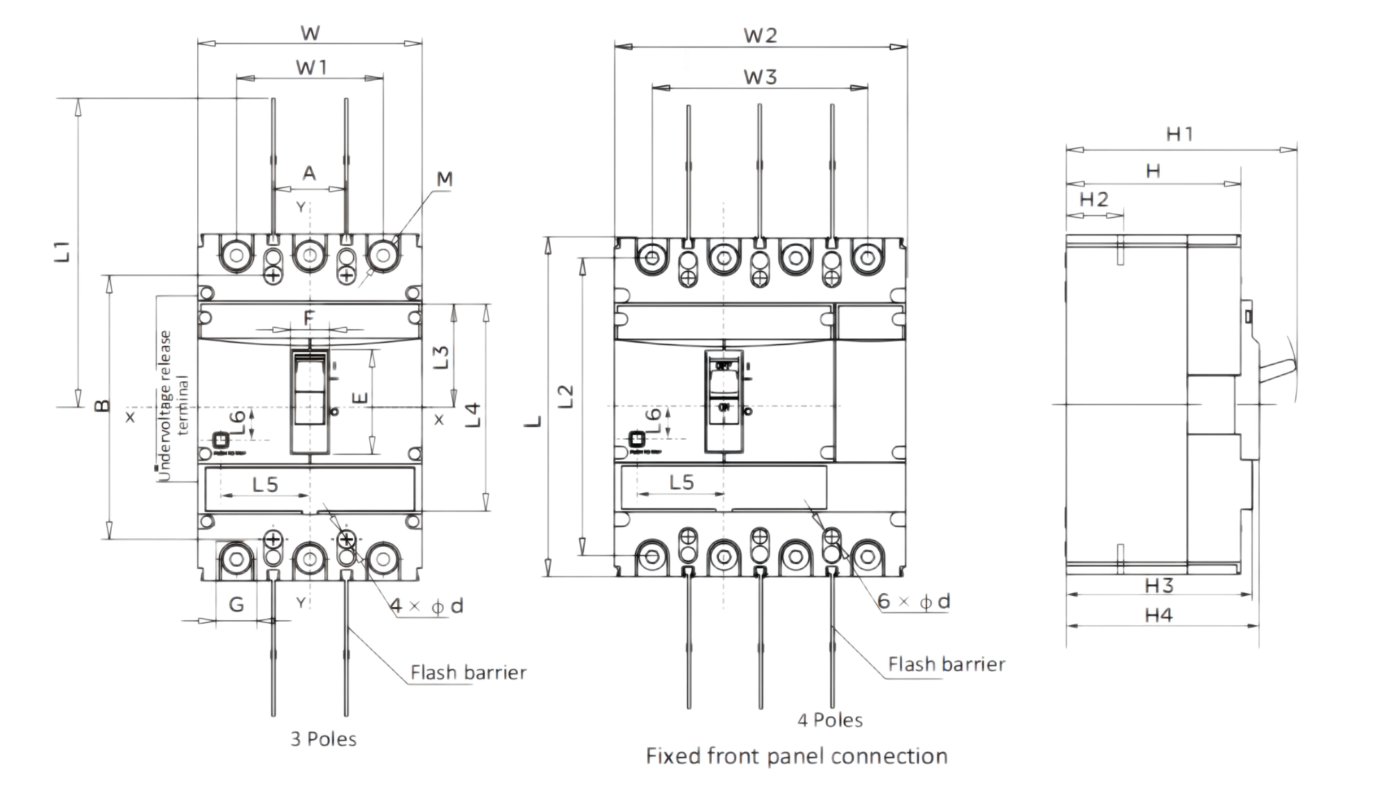
Overall dimension of front board wiring to see below diagram (X-X, Y-Y is the center of the circuit breaker)

| Model No. | Front board wiring | Button Position | ||||||||||||||||||
| W | W1 | W2 | W3 | L | L1 | L2 | L3 | L4 | H | H1 | H2 | H3 | H4 | H5 | E | F | G | L5 | L6 | |
| RDM5E-125 | 92 | 60 | - | - | 150 | 125 | 132 | 43 | 92 | 82 | 112 | 29 | 29 | 93 | 96 | 43 | 19 | 18 | 22 | 16 |
| RDM5E-250 | 107 | 70 | 142 | 105 | 165 | 136 | 144 | 52 | 104 | 85 | 115 | 23 | 23 | 90.5 | 94 | 50 | 19 | 23 | 42.5 | 15.5 |
| RDM5E-400 | 150 | 96 | 198 | 144 | 257 | 228 | 224 | 69 | 159 | 99 | 152 | 38 | 38 | 104 | 115 | 80 | 42 | 31 | 57.5 | 30 |
| RDM5E-800 | 210 | 140 | 280 | 210 | 280 | 240 | 243 | 80 | 178 | 103 | 158 | 41 | 44 | 112 | 122 | 82 | 42 | 44 | 53 | 24.5 |
Panel operation handle dimension

| Model No. | code | ||
| W4 | L8 | L9 | |
| RDM5E-125 | 23 | 24 | 40 |
| RDM5E-250 | 23 | 30 | 44 |
| RDM5E-400 | 47 | 39 | 66 |
| RDM5E-800 | 47 | 42 | 66 |
RDM5E Series back board wiring installation board hole-opening dimension

RDM5E series back-board wiring overall and installation dimension

RDM5E-125~800 Back-board wiring overall and installation board hole-opening dimension
| Model No. | Code | |||||||||
| H3 | H4 | D | W | L2 | d2 | A | B | C | d1 | |
| RDM5E-125 | 40 | 73 | M8 | 30 | 132 | 24 | 30 | 108 | 60 | 5.5 |
| RDM5E-250 | 46 | 79 | M10 | 35 | 145 | 15 | 35 | 126 | 70 | 5.5 |
| RDM5E-400 | 46 | 83 | φ12 | 48 | 224 | 32 | 44 | 194 | 94 | 7 |
| RDM5E-800 | 47 | 87 | φ16 | 70 | 243 | 48 | 70 | 243 | 70 | 7.5 |
Front board wiring installation board hole-opening dimension (X-X, Y-Y is the center of the circuit breaker)

| Model No. | RDM5E-125 | RDM5E-250 | RDM5E-400 | RDM5E-800 | |||||
| Pole | 3 | 4 | 3 | 4 | 3 | 4 | 3 | 4 | |
| Installation board hole opening dimension(mm) | A | 30 | 60 | 35 | 70 | 44 | 94 | 70 | 140 |
| B | 129 | 126 | 194 | 243 | |||||
| d | 4.5 | 4.5 | 7 | 7 | |||||
Back board wiring installation board hole-opening dimension (X-X,Y-Y is the center of the circuit breaker)

| Model No. | RDM5E-125 | RDM5E-250 | RDM5E-400 | RDM5E-800 | |||||
| Pole | 3 | 4 | 3 | 4 | 3 | 4 | 3 | 4 | |
| Installation board hole opening dimension (mm) |
A | 60 | - | 70 | - | 96 | - | 140 | - |
| A1 | - | 90 | - | 105 | - | 144 | - | 210 | |
| B | 30 | - | 35 | - | 44 | - | 70 | - | |
| B1 | - | 60 | - | 70 | - | 94 | - | 70 | |
| C | 108 | 122 | 194 | 243 | |||||
| D | 132 | 145 | 224 | 243 | |||||
| φ1 | 22 | 24 | 32 | 48 | |||||
| φ2 | 5.5 | 5.5 | 7 | 7 | |||||
RDM5E series plug-in type front board overall dimension

RDM5E-125~800 plug-in type front board circuit breaker overall dimension
| Model No. | Code | ||||||||||
| A | G | K | H | H₁ | H₂ | H3 | L1 | L2 | AM | BM | |
| RDM5E-125 | 172 | 95 | 38.5 | 50.5 | 35 | 16.5 | 61 | 185 | 217 | M6 | M8 |
| RDM5E-250 | 183 | 95 | 44 | 52 | 35 | 18 | 65 | 230 | 259 | M6 | M10 |
| RDM5E-400 | 276 | 170 | 53 | 79.5 | 67 | 18 | - | 322 | 352 | M6 | M10 |
| RDM5E-800 | 303 | 179 | 62 | 87.5 | 60.5 | 28 | 118 | 375 | 405 | M10 | M12 |
Plug-in type front board wiring installation board hole-opening dimension (X-X,Y-Y is the center of the circuit breaker)

RDM5E-125-800 Plug-in type front board wiring installation board hole opening dimension
| Model No. | RDM5E-125 | RDM5E-250 | RDM5E-400 | RDM5E-800 | |
| Pole | 3 | 3 | 3 | 3 | |
| Installation board hole opening dimension (mm) |
B | 66 | 70 | 115 | 90.5 |
| B1 | 50 | 60 | 65 | ||
| C | 60 | 64 | 135 | 144.5 | |
| C1 | 35 | 35 | - | 80 | |
| d | 6.5 | 6.5 | 6.5 | 11 | |
RDM5E series plug-in type back board overall dimension and installation board hole-opening dimension

RDM5E-125~800 Plug-in type back board circuit breaker overall dimension
| Model No. | Code | ||||||||||
| A | G | K | L1 | H | H1 | H2 | H3 | H4 | AM | BM | |
| RDM5E-125 | 168 | 92 | 38 | 132 | 48 | 32.5 | 32.5 | 18 | 17 | M6 | M8 |
| RDM5E-250 | 186 | 95 | 45.5 | 145 | 49.5 | 33.5 | 34 | 17 | 17 | M6 | M8 |
| RDM5E-400 | 280 | 171 | 54.5 | 224 | 59.5 | 40 | 44 | 23.5 | 20 | M8 | M12 |
| RDM5E-800 | 305 | 181 | 62 | 243 | 87 | 60 | - | - | 28 | M10 | M14 |
Plug in type back board wiring installation board hole-opening dimension (X-X,Y-Y is the center of circuit breaker)

RDM5E-125~800 Plug-in type back board wiring installation board hole-opening dimension
| Model No. | RDM5E-125 | RDM5E-250 | RDM5E-400 | RDM5E-800 | |||||
| Pole | 3 | 4 | 3 | 4 | 3 | 4 | 3 | 4 | |
| Installation board hole opening dimension (mm) |
A | 91 | - | 107 | - | 149 | - | 210 | - |
| A1 | - | 126 | - | 145 | - | 200 | - | 280 | |
| B | 60 | - | 70 | - | 60 | - | 90 | ||
| B1 | - | 90 | - | 105 | - | 108 | - | 162 | |
| C | 56 | 54 | 129 | 146 | |||||
| K | 38 | 45.5 | 54.5 | 62 | |||||
| E | 92 | 95 | 171 | 181 | |||||
| d | 6.5 | 6.5 | 8.5 | 11 | |||||
| Rated current of shell frame grade Inm (A) | 125 | 250 | 400 | 800 | |||||
| Rated current In (A) | 32、63、125 | 250 | 400 | 630、800 | |||||
| Current setting value IR (A) | (12.5~125)+Close | (100~250)+Close | (160~400)+Close | (250~800)+Close | |||||
| Breaking capacity level | M | H | M | H | M | H | M | H | |
| Number of poles | 3P、4P | ||||||||
| Rated frequency (Hz) | 50 | ||||||||
| Rated insulation voltage Ui (V) | AC1000 | ||||||||
| Rated impulse withstand voltage Uimp (V) | 12000 | ||||||||
| Rated working voltage Ue (V) | AC400/AC690 | ||||||||
| Arcing distance (mm) | ≤50 | ≤50 | ≤100 | ≤100 | |||||
| Short-circuit breaking capacity level | M | H | M | H | M | H | M | H | |
| Rated limit short-circuit breaking capacity Icu (kA) | AC400V | 50 | 85 | 50 | 85 | 65 | 100 | 75 | 100 |
| AC690V | 35 | 50 | 35 | 50 | 42 | 65 | 50 | 65 | |
| Rated operating short-circuit breaking capacity Ics (kA) | AC400V | 20 | 20 | 20 | 20 | 20 | 20 | 20 | 20 |
| AC690V | 10 | 10 | 10 | 10 | 15 | 15 | 15 | 15 | |
| Rated short-time withstand current Icw (kA/1s) | 1.5 | 3 | 5 | 10 | |||||
| Use category | A | A | B | B | |||||
| Compliance with standards | IEC60497-2/GB/T14048.2 | ||||||||
| Applicable working ambient temperature | -35°C~+70°C | ||||||||
| Electrical life (times) | 8000 | 8000 | 7500 | 7500 | |||||
| Mechanical life (times) | 20000 | 20000 | 10000 | 10000 | |||||
| Front panel connection | █ | █ | █ | █ | |||||
| Back panel connection | █ | █ | █ | █ | |||||
| Plug-in wiring | █ | █ | █ | █ | |||||
| Undervoltage release | █ | █ | █ | █ | |||||
| Shunt release | █ | █ | █ | █ | |||||
| Auxiliary contact | █ | █ | █ | █ | |||||
| Alarm contact | █ | █ | █ | █ | |||||
| Electric operating mechanism | █ | █ | █ | █ | |||||
| Manual operating mechanism | █ | █ | █ | █ | |||||
| Intelligent control module | █ | █ | █ | █ | |||||
| Test power module | █ | █ | █ | █ | |||||
| Communication function | █ | █ | █ | █ | |||||
| Time setting | █ | █ | █ | █ | |||||
See Figure 1 for the overall dimensions of the front-plate wiring (X-X and Y-Y are the center of the circuit breaker)
| Model | Front panel connection | Button location |
|||||||||||||||||
| W | W1 | W2 | W3 | L | L1 | L2 | L3 | L4 | H | H1 | H2 | H3 | H4 | E | F | G | L5 | L6 | |
| RDM5E-125 | 92 | 60 | 122 | 90 | 150 | 125 | 132 | 43 | 92 | 82 | 112 | 29 | 93 | 96 | 43 | 19 | 18 | 22 | 16 |
| RDM5E-250 | 107 | 70 | 142 | 105 | 165 | 136 | 144 | 52 | 104 | 85 | 115 | 23 | 90.5 | 94 | 50 | 19 | 23 | 42.5 | 15.5 |
| RDM5E-400 | 150 | 96 | 198 | 144 | 257 | 256 | 224 | 9 | 159 | 99 | 152 | 38 | 104 | 115 | 80 | 42 | 1 | 57.5 | 30 |
| RDM5E-800 | 210 | 140 | 280 | 210 | 280 | 240 | 243 | 80 | 178 | 102 | 158 | 41 | 112 | 122 | 82 | 42 | 44 | 53 | 24.5 |