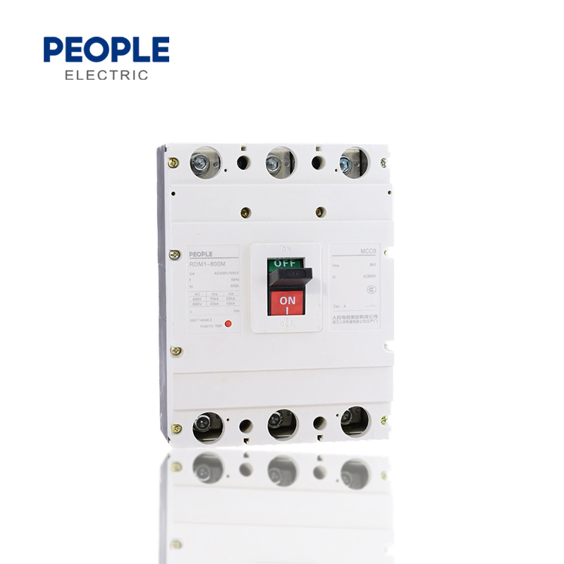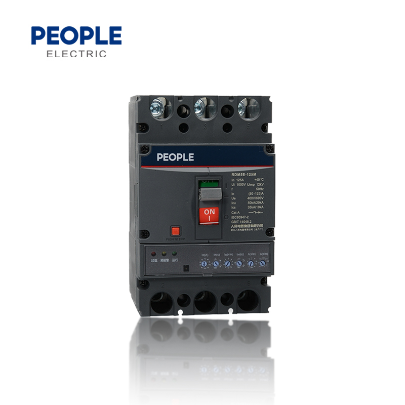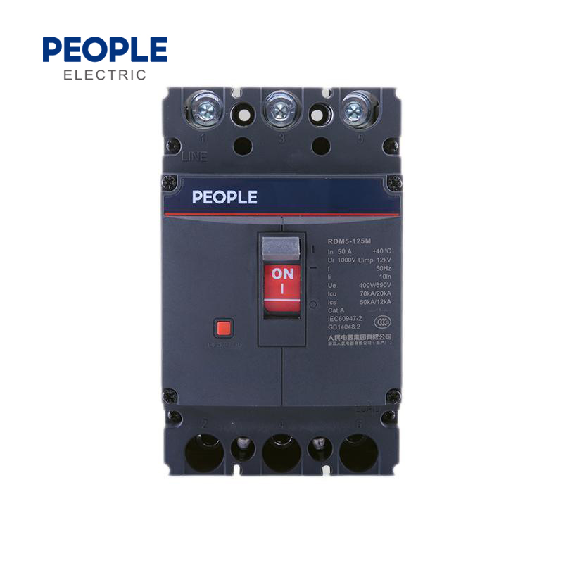


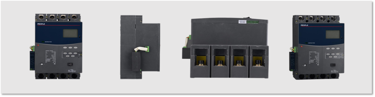
| Panel Interpretation | |
| 1 | Trademark |
| 2 | Product model |
| 3 | Technical parameters |
| 4 | Conformed standard |
| 5 | CCC/CE Symbol |
| 6 | Company Name |
| 7 | Handle |
| 8 | Terminal screws |
| 9 | Tripping button |
| 10 | Cover |
| 11 | Middle cover |
| 12 | Accessory mounting holes |
| 13 | Base |

1.Pollution level: Level 3
2.Ambient temperature: ambient air temperature is -5℃~+40℃, and the average value for 24 hours does not exceed +35°C
3.Relative humidity: does not exceed 50% when the ambient air temperature is +40°C; higher relative humidity can be achieved at lower temperatures; for example, the average maximum relative humidity in the wettest month is 90%.,and the average minimum temperature of the month is +20°C.Measures should be taken to deal with condensation occasionally caused by temperature changes
4.Altitude: does not exceed 2000m
5.Main circuit installation category:Ⅱ
6.Electromagnetic environment:A
| Frame size Inm(A) | 63A | 125 | 160 | 250 | 400 | 630 | 800 | |||||||||||||||
| Rated current ln(A) | 10、16、20、25、32、40、50、63 | 10、16、20、25、32、40、50、63、80、100、125 | 63、80、100、125、160 | 100、125、160、180、200、225、250 | 200、225、250、315、350、400 | 400、500、630 | 630、700、800 | |||||||||||||||
| Pole(P) | 2、3、4 | 3、4 | 2、3、4 | 3、4 | 3、4 | 2、3、4 | 3、4 | 2、3、4 | 3、4 | 3、4 | ||||||||||||
| Rated frequency(Hz) | 50 | |||||||||||||||||||||
| Rated insulation voltage Ui(V) | AC1000 | |||||||||||||||||||||
| Rated impulse withstand voltage(V) | 8000 | 12000 | ||||||||||||||||||||
| Rated working voltage Ue(V) | AC400/AC690 | |||||||||||||||||||||
| Arcing distance(mm) | ≤50 | ≤50 | ≤50 | ≤50 | ≤100 | ≤100 | ≤100 | |||||||||||||||
| Short-circuit breaking capacity level | L | M | S | L | M | H | S | L | M | S | L | M | H | L | M | H | L | M | H | L | M | H |
| Rated ultimate/rated operating breaking capacity Icu/Ics(AC400V) | 25/15 | 35/25 | 15/10 | 25/15 | 35/25 | 50/35 | 15/10 | 25/15 | 35/25 | 15/10 | 25/15 | 35/25 | 50/35 | 35/25 | 50/35 | 70/50 | 35/25 | 50/35 | 70/50 | 35/25 | 50/35 | 70/50 |
| Rated ultimate/rated operating breaking capacity Icu/Ics(AC690V) | / | / | / | / | 15/8 | 15/8 | / | 15/8 | 15/8 | / | / | 15/8 | 15/8 | / | 20/12 | 20/12 | / | 20/12 | 20/12 | / | 20/12 | 20/12 |
| Category | A | |||||||||||||||||||||
| Standards | IEC60947-2 | |||||||||||||||||||||
| Environment temperature | -5℃~+40℃ | |||||||||||||||||||||
| Electrical life(times) | 8000 | 7500 | ||||||||||||||||||||
| Mechanical life(times) | 20000 | 20000 | 20000 | 20000 | 10000 | 10000 | 10000 | |||||||||||||||
| Shunt release | ■ | ■ | ■ | ■ | ■ | ■ | ■ | |||||||||||||||
| Undervoltage release | ■ | ■ | ■ | ■ | ■ | ■ | ■ | |||||||||||||||
| Alarm contact | ■ | ■ | ■ | ■ | ■ | ■ | ■ | |||||||||||||||
| Auxiliary contact | ■ | ■ | ■ | ■ | ■ | ■ | ■ | |||||||||||||||
Note: the operating voltage of 2-pole products with RDM5-63, 125, 160, and 250 frames is less than or equal to 400V and below.
| “N” Pole type of circuit breaker | |
| Type A | The N pole is not equipped with an overcurrent release element, and the N pole is always connected and does notclose or open together with the other three poles. |
| Type B | The N pole is not eauipped with an overcurrent release element, and the N pole is closed and opened together withthe other three poles (the N pole is closed first and then opened) |
| Ambient temperature/ Factor/ Model No. | +40°C | +45°C | +50°C | +55°C | +60°C | +65°C | +70°C |
| Derating factor | Derating factor | Derating factor | Derating factor | Derating factor | Derating factor | Derating factor | |
| RDM5-63 | 1ln | 0.959ln | 0.918ln | 0.877ln | 0.835ln | 0.794ln | 0.752ln |
| RDM5-125 | |||||||
| RDM5-160 | |||||||
| RDM5-250 | 1ln | 0.985ln | 0.968ln | 0.952ln | 0.935ln | 0.919ln | 0.887ln |
| RDM5-400 | 1ln | 0.978ln | 0.957ln | 0.936ln | 0.915ln | 0.894ln | 0.873ln |
| RDM5-630 | 1ln | 0.978ln | 0.957ln | 0.936ln | 0.915ln | 0.894ln | 0.873ln |
| RDM5-800 | 1ln | 0.978ln | 0.957ln | 0.936ln | 0.915ln | 0.894ln | 0.873ln |
The thermal release of the product has an inverse time characterisic, and the electromagneic release has an instantaneous acion characteristic. The action characteristics are shown in the table below.
| Distribution protection | Motor protection | ||||||
| Rated current lnA) | Thermal magnetic release | Instantaneous action current (A) | Rated current ln(A) | Thermal magnetic release | |||
| 1.05ln (cold state) non-release time (h) | 1.30ln (heat state) release time(h) | 1.0ln (cold state) non-release time (h) | 1.2ln (heat state) release time(h) | Instantaneous action current (A) | |||
| 10≤ln≤63 | 1 | 1 | 10ln±20% | 10≤ln≤630 | 2 | 2 | 12ln±20% |
| 63<ln≤125 | 2 | 2 | 5ln±20% 10ln±20% |
||||
| 125<ln≤800 | 2 | 2 | |||||
Note: In the RDM5-63 and RDM5-125S/L specifications, the operaing current of the electromagnetic release In=40A is 500A±20%.
Curve graph 1:RDM5-63,125,160 40A~125A Power distribution protection (black line), motor protection (red line)
Curve graph 2:RDM5-250 power distribution protection (black line),motor protection(red line)
Note: RDM5-63, RDM5-125S/L model specification ln=40A electromagnetic release action current is 500A±20%

Curve graph 3:RDM5-400 power distribution protection (black line),motor protection(red line)
Curve graph 4:RDM5-630 Power distribution protection (black line),motor protection(red line)

Curve graph 5:RDM5-800 630A power distribution
Curve graph 6:RDM5-800 700A,800A power distribution


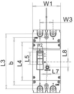
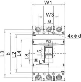
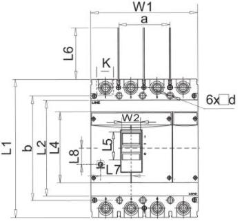
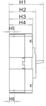
| Model No. | Pole | Front Panel Wiring | Installation Size | Button Position | ||||||||||||||||||
| L1 | L2 | L3 | L4 | L5 | L6 | W1 | W2 | W3 | H1 | H2 | H3 | H4 | H5 | H6 | K | a | b | d | L7 | L8 | ||
| RDM5-63L/M RDM5-125S/L |
2 | 130 | - | 116.5 | 85 | - | 49.5 | 50 | 11 | 25 | 83 | 71 | - | 57 | 24.5 | 24.5 | 18.5 | - | 111 | 3.5 | 17 | 20 |
| 3 | 130 | - | 116.5 | 85 | - | 49.5 | 75 | 11 | 50 | 83 | 71 | - | 57 | 24.5 | 24.5 | 18.5 | 25 | 111 | 3.5 | 16.5 | 20 | |
| 4 | 130 | - | 116.5 | 85 | - | 49.5 | 100 | 11 | 75 | 83 | 71 | - | 57 | 24.5 | 24.5 | 18.5 | 50 | 111 | 3.5 | 16.5 | 20 | |
| RDM5-125M/H | 2 | 152 | - | 132 | 88 | 31 | 52 | 62 | 14.5 | 30 | 109.5 | 96 | - | 82 | 28.5 | 28.5 | 18 | - | 129 | 4.5 | 1 | 6.5 |
| 3 | 152 | - | 132 | 88 | 31 | 52 | 92 | 14.5 | 60 | 110 | 96 | - | 82 | 28.5 | 28.5 | 18 | 30 | 129 | 4.5 | 22 | 15.5 | |
| 4 | 152 | - | 132 | 88 | 31 | 65 | 122 | 14.5 | 90 | 110 | 96 | - | 82 | 28.5 | 28.5 | 18 | 60 | 129 | 4.5 | 22 | 16.5 | |
| RDM5-160S/L/M | 2 | 150 | - | 133 | 88 | 31 | 52 | 62 | 14.5 | 30 | 93 | 79 | - | 65 | 23.5 | 23.5 | 22 | - | 129 | 3.5 | 1 | 16.5 |
| 3 | 150 | - | 133 | 88 | 31 | 52 | 92 | 14.5 | 60 | 93 | 79 | - | 65 | 23.5 | 23.5 | 22 | 30 | 129 | 3.5 | 22 | 15.5 | |
| 4 | 150 | - | 133 | 88 | 31 | 52 | 122 | 14.5 | 90 | 93 | 79 | - | 65 | 23.5 | 23.5 | 22 | 60 | 129 | 3.5 | 22 | 16.5 | |
| RDM5-250S/L | 2 | 165 | - | 145.5 | 102 | 33 | 53 | 75 | 14 | 35 | 96 | 76 | - | 67 | 23 | 23 | 25 | - | 126 | 4.5 | 2.5 | 15.5 |
| 3 | 165 | - | 145.5 | 102 | 33 | 53 | 107 | 14 | 70 | 96 | 76 | - | 67 | 23 | 23 | 25 | 35 | 126 | 4.5 | 42.5 | 5.5 | |
| 4 | 165 | - | 145.5 | 102 | 33 | 53 | 142 | 14 | 105 | 96 | 76 | - | 67 | 23 | 23 | 25 | 70 | 126 | 4.5 | 43 | 15.5 | |
| RDM5-250M/H | 2 | 165 | - | 145 | 102 | 33 | 53 | 75 | 14 | 35 | 112.5 | 94 | - | 85 | 22 | 22 | 24 | - | 126 | 4.5 | 2.5 | 15.5 |
| 3 | 165 | - | 145 | 102 | 33 | 53 | 107 | 14 | 70 | 115 | 94 | - | 85 | 23 | 23 | 23 | 35 | 126 | 4.5 | 42.5 | 15.5 | |
| 4 | 165 | - | 145 | 102 | 33 | 53 | 142 | 14 | 105 | 115 | 94 | - | 85 | 23 | 23 | 23 | 70 | 126 | 4.5 | 43 | 15 | |
| RDM5-400L/M/H | 3 | 258 | 178 | 224 | 132 | 53 | 100 | 150 | 35 | 96 | 152 | 115 | 101 | 99 | 38 | 38 | 31 | 44 | 194 | 7 | 57.5 | 30 |
| 4 | 258 | 179 | 224 | 132 | 53 | 100 | 198 | 35 | 144 | 152 | 115 | 101 | 99 | 38 | 38 | 31 | 94 | 194 | 7 | 57.5 | 30 | |
| RDM5-630L/M/H | 3 | 270 | 185 | 235.5 | 146 | 52.5 | 100 | 182 | 35.5 | 116 | 158 | 119 | 106 | 103 | 45 | 43 | 41 | 58 | 200 | 7 | 58 | 32 |
| 4 | 270 | 185 | 235.5 | 146 | 52.5 | 100 | 240 | 35.5 | 174 | 158 | 119 | 106 | 103 | 45 | 43 | 41 | 116 | 200 | 7 | 58 | 31.5 | |
| RDM5-800L/M/H | 3 | 280 | 205 | 243 | 148 | 52 | 100 | 210 | 35 | 140 | 159 | 122 | 109 | 105 | 40.5 | 42.5 | 45 | 70 | 243 | 7 | 53 | 24.5 |
| 4 | 280 | 205 | 243 | 148 | 52 | 100 | 280 | 35 | 210 | 159 | 122 | 109 | 105 | 40.5 | 42.5 | 45 | 140 | 243 | 7 | 53 | 24.5 | |

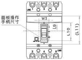
| Model Number | Dimension Code | |||
| (L11) | W3 | L9 | L10 | |
| RDM5-63L/M RDM5-125S/L |
64 | 19 | 14 | 43 |
| RDM5-125M/H RDM5-160S/L/M |
- | 23 | 24 | 40 |
| RDM5-250S/L/M/H | - | 23 | 30 | 44 |
| RDM5-400L/M/H | - | 47 | 39 | 66 |
| RDM5-630L/M/H | - | 47 | 39 | 66 |
| RDM5-800L/M/H | - | 47 | 42 | 66 |
Function

When the circuit breaker is at the statues of opening or free tripping, F12 and F11 is connected, F14 and F11 is breaking; When the circuit breaker is at the closing statues, F12 and F11 is breaking, F14 and F11 is connecting.
Each set of auxiliary contacts is not electrically separated, and the parameters of the auxiliary contacts are shown in the table below.
| Detailed Parameters | ||
| When the circuit breaker is at the position of “Opening" |  |
Frame size of circuit breaker is 400A and above |
 |
Frame size of circuit breaker is 250A and below | |
| When the circuitbreaker is at the position of “Closing” | When is at the "Opening", the contacts in the ON status turns to the OFF status When is at the "Opening", the contacts in the OFF status turns to the ON status |
|
Electrical Characteristics
| Operating voltage (V) | AC | DC | ||||||
| 24 | 48 | 110 | 240/415 | 24 | 48 | 110/220 | ||
| Rated current(A) | AC-15 | 6 | 6 | 5 | 2 | - | - | - |
| DC-13 | - | - | - | - | 2 | 1.2 | 0.25 | |
Wiring diagram
The auxiliary contact can form a control loop with the indicator light. Through the indicator light, the operator can know the opening and closing position of the circuit breaker without opening the power distribution cabinet.

The alarm contact is mainly used to provide a signal when the circuit breaker load is overoaded, short-circuited or undervoltage and other faults or free tripping occur.
When the circuit breaker is in the opened or closed state,B12 and B11 are connected, and B14 and B11 are disconnected.
When the circuit breaker is in a tripped state,B12 and B11 are disconnected, and B14 and B11 are connected.
Function

1.Overload or short-circuit faults
2.Artificial test button tripping
3.Shunt release action
4.Circuit failure, the action of the undervoltage tripper indicates the opening and closing status of the circuit breaker
| Detailed Parameters | |
| When the circuit breaker is at the position of “Opening" “Closing’ | 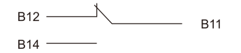 |
| When the circuit breaker is at th eposition of “Free tripping" alarming | 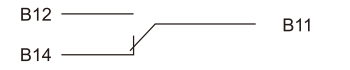 |
Wiring diagram
The alarm contact can be connected to the indicator light, buzzer, etc., and the operator can be notified in time when the circuit breaker is tripped.

Parameter of Auxiliary Contacts and Alarming Contacts
| Classification | Rated current of frame size | Setting heating current A | AC-15 | DC-13 | |||
| Rated voltage((V) | Rated frequency(Hz) | Rated current(A) | Rated voltage((V) | Rated current(A) | |||
| Auxiliary contacts | Inm≤250 | 3 | 400 | 50 | 0.3 | 230 | 0.15 |
| Inm≥400 | 3 | 0.4 | 0.15 | ||||
| Alarming contacts | 125≤Inm≤800 | 3 | 0.3 | 0.15 | |||


Shunt release is an accessory of remote control the products to open, when the power supply is equal to the any voltage among 70%~110% of the rated control power supply voltage, the shunt release can reliably action.
Electrical characteristics
| Model No. | Power consumption of shunt coil (W) | ||
| AC400V | AC230V | DC24V | |
| RDM5-63,125,160 | 96.8 | 73 | 91.2 |
| RDM5-250 | 112 | 68.6 | 85.3 |
| RDM5-400,630,800 | 68 | 58.2 | 100 |
Action characteristics
| Operating voltage of reliably action | 70%~110% Us | |
| Power-on time(pulse type) | Min. value | 10ms |
| Max. value | 1s | |
| Response time | 300ms | |
| Operation cycles | 1000 | |
Wiring diagram
K: The micro switch connected in series with the col inside the shunt release,is the NC contact, after the circuit breaker opened, this contact will break by itself, and close when the circuit breaker is closed.
When using the shunt release with the rated control power voltage of DC24v, the maximum length of the copper wire (the length of each of the two wires), must satisfy with the requirements of the tables.
| Conductor sectional area/ Voltage DC24V |
1.5mm² | 25mm² |
| 100%Ue | 150m | 250m |
| 80%Ue | 100m | 1600m |


DC24V
AC 50Hz 230V,400V
It can realize the undervoltage protection functions of this circuit breaker, to break thie circuit breaker when the power voltage is over low,and protecting the equipments. When its power voltage reduces toone specified range, it can make the circuit breaker realize non-delaybreaking breaking.When the voltage reduces to the 70%~35% of the rated control voltage, the undervoltage release should action; When it is lower than 35% of the release's rated voltage, the undervoltage release should prevent the circuit breaker closed; Within the 85%~110% of the rated control power power voltage, the undervoltage release should ensure the circuit breaker can reliably close.
Rated value of undervoltage release: AC50Hz,230V,400V.
Notice: the circuit breaker with the undervoltage release, it can only re-trip and close under the situation of the release is electrified with rated voltage.

Applicable Voltage and Power Consumption
| Applicable Voltage and Power Consumption | |
| Rated control powersupply voltage (Us) | AC 220~240V |
| AC 380~415 | |
| Power consumption (hold) | 5W |
Wiring Diagram for Undervoltage Release

Electrical characteristics
| Model No. | Power consumption of undervoltage coil(W) | |
| AC400V | AC230V | |
| RDM5-63,125,160 | 4 | 3.1 |
| RDM5-250 | 4.3 | 3.3 |
| RDM5-400,630 | 3.6 | 2.5 |
| RDM5-800 | 2 | 1.6 |
Action characteristics
| Action condition | Reliably breaking | 35%~70% |
| Prevent closing | ≤35% | |
| Reliably closking | ≥85% | |
| Response time | 1s | |
| Operation cycle | 1000 | |

Functions
口 Button control the circuit breaker opening and closing
口 Both can be freely selection of motor opening and closing or human operation manually opening and closing
口 With the opening and closing indication as well as freely tripping indication
Operation
Selecting the operation type through manual/automatic rotate switch
口 Automatic operation
Switch “manual/automatic switch" to the automatic" position, remotely give the signal of "closing or opening",to realize the connecting and breaking of the circuit breaker
口 Manual operation
Switch "manual/automatic switch" to the "manual" position, rotate operation handle to realize the connecting and breaking of the circuit breaker
Application
口 Local motor operation, centralized operation, and automatically control
口 Normal/backup power conversion, or switch to the backup power supply, to optimize the energy costs, etc.
口 It is applicable for the circuit breaker remote motor closing, breaking and re-bulk as wel as the occasions of automatic control
口 Rated voltage of motor operation mechanism: AC400V,AC230V, DC220V
口Operating voltage range of motor operation mechanism: 85%~110%Ue
Motor operation mechanism type
口 CD2 AC,DC Type motor operation mechanism
Allowable voltage range of CD2 Motor operation mechanism:
口 CD2: the operation frequency for 125~250A is not over 180 times/h, action time≤0.7s
口 CD2: the operation frequency for 400~800A is not over 60 times/h, action times≤1s
口 D Rated control power voltage: when at 400V, the allowable voltage range: 320~440VAC
口 According to the diferent operating forces of the circuit breaker, the electric operating mechanism of the switch with relatively small force can operate normally
Structural form of the electric operating mechanism
| Category/Model | RDM5-63,125,250,400,630,800 |
| Structure form | Electric motor |
| Voltage | 50Hz,230V,400V |
Note: Afer the circuit breaker with the elecltric operation mechanism is tripped, the electic operaing mechanism must make the circuit breaker re-tip, and then closing.
The height of RDM5 series circuit breaker motor operating mechanism is shown in the Table.
| Model | RDM5-63L,M RDM5-125L |
RDM5-125M RDM5-160L,M |
RDM5-250L, M, H | RDM5-400L, M, H | RDM5-630L, M, H | RDM5-800L, M, H |
| Height H | 95 | 94 | 90 | 145 | 145 | 147 |
The height of RDM5 series circuit breaker motor operating mechanism is shown in Table

Schematic diagram of CD2 motor installation and operation:


Note:After the circuit breaker with the electric operating mechanism is tripped and tripped, the electric operating mechanism must first open the gate before it can close the gate.

According to human mechanics, the rotating handle adopts an unique designand transmission structure. The closing and re-buckling of the circuit breaker are realized through the rotating handle. Flexible operation, smooth, low operating force,easy installation.
The position of the rotation handle exactly indicates the position of the circuit breaker contacts: open, closed or free trip.
Classification of rotating handle
口 Direct rotating handle (RHD)
口 Extended rotating handle(ERH)
Characteristics of rotating handle
口 When the circuit breaker is at the closing status, under the function of rotating handle, it cannot opening the cabinet door
口 If require to emergently open the cabinet door, it can use the emergent unlock device on the handle to open the cabinet door
口 Corresponding to different specifications of circuit breakers, with each matching extended hand-operated handles, their opening size of the door panel are the same
口 Small operation force, high reliably


Installation diagram
1. Align the direction of manual installation; 2. Tighten the mounting screws; 3. Install anextended screw; 4.Fixed screw; 5. Install an extended handle
Note: The default standard confiquration of the screw length is 150mm at the factory. If you need other special customization, please contact the factory (increase or decrease in units of 50mm).

Rotating hand mechanism
When the manual mechanism is installed, first open the hole according to the size shown, and turn the handle "OFF" on the door pane of the switch cabinet to indicate that the handle is fixed in the horizontal position. Then try to operate the handle, the rotation should be fexilble, and the circuit breaker should be closed when the handle is in the horizontal position, and the circuit breaker should be closed when the handle is in the vertical position.

Size diagram of manual operation mechanism for 63~800A
Rotating hand mechanism
When the manual mechanism is installed, first open the hole according to the size shown, and turn the handle "OFF" on the door pane of the switch cabinet to indicate that the handle is fixed in the horizontal position. Then try to operate the handle, the rotation should be fexilble, and the circuit breaker should be closed when the handle is in the horizontal position, and the circuit breaker should be closed when the handle is in the vertical position.

Square extension rotating handle opening size diagram
| Model No. | RDM5-63L,M RDM5-125L |
RDM5-125M,H RDM5-160L,M |
RDM5-250L, M, H | RDM5-400L, M, H | RDM5-630L, M, H | RDM5-800L, M, H |
| Installation size H | 51 | 61 | 57 | 88 | 88 | 87 |
| The Y value of the operating handle relative to the center of the circuit breaker | 0 | 0 | 0 | 0 | 0 | 0 |
Phase separator
The phase separator can enhance the insulation performance of the phase conductor, even after the switch is installed, it can be installed from the front slot. The phase separator is standard at the factory, and a circuit breaker has 2 pieces(2P),4 pieces (3P), and 6 pieces(4P).

Recommended pre-making busbar dimension

RDM5 series recommended pre-making busbar dimensions
| Model No. | RDM5-125S | RDM5-65L/M RDM5-125L |
RDM5-125M/H RDM5-160S/L/M |
RDM5-160S/L/M | RDM5-400S/L/M | RDM5-630L, M, H | RDM5-800L, M, H |
| Contact screw specifications | M6 | M8 | M8 | M8 | M12 | M12 | M12 |
| Torque( N·m ) | 5 | 8 | 10 | 10 | 20 | 26 | 28 |
| Frame grade rated current l nm(A) | 63 | 125 | 160 | 250 | 400 | 630 | 800 | ||||||||||||||||||
| Rated currentln(A) | 10、16、20、25、32、40、50、63 | 10、16、20、25、32、40、50、63、80、100、125 | 63、80、100、125、160 | 100、125、160、180、200、225、250 | 200、225、250、315、350、400 | 400、500、630 | 630、700、800 | ||||||||||||||||||
| Pole(P) | 2、3、4 | 3、4/2、3、4/3、4 | 3、4/2、3、4 | 3、4/2、3、4/3、4 | 3、4 | ||||||||||||||||||||
| Rated frequency(Hz) | 50 | ||||||||||||||||||||||||
| Rated insulation voltageUi(V) | AC1000 | ||||||||||||||||||||||||
| Rated impulse withstand voltage(V) | 12000 | ||||||||||||||||||||||||
| Rated working voltageUe(V) | 400V | AC400/AC690 | |||||||||||||||||||||||
| Arcing distance(mm) | ≤50 | ≤50 | ≤50 | ≤50 | ≤100 | ≤100 | ≤100 | ||||||||||||||||||
| Short-circuit breaking capacity | L | M | S | L | M | H | S | L | M | S | L | M | H | L | M | H | S | L | M | H | L | M | H | ||
| Rated Limit/Rated breaking capacity lcu/lcs(AC400V) | 25/15 | 35/25 | 25/18 | 50/35 | 70/50 | 100/70 | 25/18 | 35/23 | 50/35 | 25/18 | 50/35 | 70/50 | 100/70 | 50/50 | 70/70 | 100/75 | 50/35 | 50/50 | 70/70 | 100/75 | 65/65 | 75/75 | 100/75 | ||
| Rated Limit/Rated breaking capacity lcu/lcs(AC690V) | / | / | / | 20/10. | 20/12. | 30/15. | / | 10/5. | 15/8. | / | 20/10. | 20/12. | 30/15 | 20/10. | 25/15 | 35/18 | / | 20/10. | 25/15 | 35/18 | 20/10. | 25/15 | 35/20 | ||
| Use category | A | ||||||||||||||||||||||||
| Standards compliant | IEC60947-2 GB/T14048-2 | ||||||||||||||||||||||||
| Suitable for working environment temperature | -5℃+40℃ | ||||||||||||||||||||||||
| Electrical life(times) | 8000 | 7500 | |||||||||||||||||||||||
| Mechanical life(times) | 20000 | 20000 | 20000 | 20000 | 10000 | 10000 | 10000 | ||||||||||||||||||
| Shunt release | ■ | ■ | ■ | ■ | ■ | ■ | ■ | ||||||||||||||||||
| Undervoltage release | ■ | ■ | ■ | ■ | ■ | ■ | ■ | ||||||||||||||||||
| Alarm contact | ■ | ■ | ■ | ■ | ■ | ■ | ■ | ||||||||||||||||||
| Auxiliary contact | ■ | ■ | ■ | ■ | ■ | ■ | ■ | ||||||||||||||||||
2 poles 3 poles
4 poles Side
| Product model | Pole | Front panel wiring | Installation size | Button position | ||||||||||||||||||
| L1 | L2 | L3 | L4 | L5 | L6 | W1 | W2 | W3 | H1 | H2 | H3 | H4 | H5 | H6 | K | a | b | d | L7 | L8 | ||
| RDM5-63L/M RDM5-125S/L |
2 | 130.0 | - | 116.5 | 85.0 | - | 49.5 | 50.0 | 11.0 | 25.0 | 83.0 | 71.0 | - | 57.0 | 24.5 | 24.5 | 18.5 | - | 111.0 | 3.5 | 17.0 | 20.0 |
| 3 | 130.0 | - | 116.5 | 85.0 | - | 49.5 | 75.0 | 11.0 | 50.0 | 83.0 | 71.0 | - | 57.0 | 24.5 | 24.5 | 18.5 | 25.0 | 111.0 | 3.5 | 16.5 | 20.0 | |
| 4 | 130.0 | - | 116.5 | 85.0 | - | 49.5 | 100.0 | 11.0 | 75.0 | 83.0 | 71.0 | - | 57.0 | 24.5 | 24.5 | 18.5 | 50.0 | 111.0 | 3.5 | 16.5 | 20.0 | |
| RDM5-125M/H | 2 | 152.0 | - | 132.0 | 88.0 | 31.0 | 52.0 | 62 | 14.5 | 30.0 | 109.5 | 96.0 | - | 82.0 | 28.5 | 28.5 | 18.0 | - | 129.0 | 4.5 | - | 6.5 |
| 3 | 152.0 | - | 132.0 | 88.0 | 31.0 | 52.0 | 92 | 14.5 | 60.0 | 110.0 | 96.0 | - | 82.0 | 28.5 | 28.5 | 18.0 | 30.0 | 129.0 | 4.5 | 22.0 | 15.5 | |
| 4 | 152.0 | - | 132.0 | 88.0 | 31.0 | 65.0 | 122.0 | 14.5 | 90.0 | 110.0 | 96.0 | - | 82.0 | 28.5 | 28.5 | 18.0 | 60.0 | 129.0 | 4.5 | 22.0 | 16.5 | |
| RDM5-160S/L/M | 2 | 150.0 | - | 133.0 | 88.0 | 31.0 | 52.0 | 62 | 14.5 | 30.0 | 93.0 | 79.0 | - | 65.0 | 23.5 | 23.5 | 22.0 | - | 129.0 | 3.5 | - | 16.5 |
| 3 | 150.0 | - | 133.0 | 88.0 | 31.0 | 52.0 | 92 | 14.5 | 60.0 | 93.0 | 79.0 | - | 65.0 | 23.5 | 23.5 | 22.0 | 30.0 | 129.0 | 3.5 | 22.0 | 15.5 | |
| 4 | 150.0 | - | 133.0 | 88.0 | 31.0 | 52.0 | 122.0 | 14.5 | 90.0 | 93.0 | 79.0 | - | 65.0 | 23.5 | 23.5 | 22.0 | 60.0 | 129.0 | 3.5 | 22.0 | 16.5 | |
| RDM5-250S/L | 2 | 165.0 | - | 145.5 | 102.0 | 33.0 | 53.0 | 75.0 | 14.0 | 35.0 | 96.0 | 76.0 | - | 67.0 | 23 | 23.0 | 25.0 | - | 126.0 | 4.5 | 2.5 | 15.5 |
| 3 | 165.0 | - | 145.5 | 102.0 | 33.0 | 53.0 | 107.0 | 14.0 | 70.0 | 96.0 | 76.0 | - | 67.0 | 23 | 23.0 | 25.0 | 35.0 | 126.0 | 4.5 | 42.5 | 5.5 | |
| 4 | 165.0 | - | 145.5 | 102.0 | 33.0 | 53.0 | 142.0 | 14.0 | 105.0 | 96.0 | 76.0 | - | 67.0 | 23 | 23.0 | 25.0 | 70.0 | 126.0 | 4.5 | 43.0 | 15.5 | |
| RDM5-250M/H | 2 | 165.0 | - | 145.0 | 102.0 | 53.0 | 53.0 | 75.0 | 14.0 | 55.0 | 112.5 | 94.0 | - | 85.0 | 22 | 22.0 | 24.0 | - | 126.0 | 4.5 | 2.5 | 15.5 |
| 3 | 165.0 | - | 145.0 | 102.0 | 33.0 | 53.0 | 107.0 | 14.0 | 70.0 | 115.0 | 94.0 | - | 85.0 | 23 | 23.0 | 23.0 | 35.0 | 126.0 | 4.5 | 42.5 | 15.5 | |
| 4 | 165.0 | - | 145.0 | 102.0 | 33.0 | 53.0 | 142.0 | 14.0 | 105.0 | 115.0 | 94.0 | - | 85.0 | 23 | 23.0 | 23.0 | 70.0 | 126.0 | 4.5 | 43.0 | 15.0 | |
| RDM5-400L/M/H RDM5-630S |
3 | 258.0 | 178.0 | 224.0 | 132.0 | 53.0 | 100.0 | 150.0 | 35.0 | 96.0 | 152.0 | 115.0 | 101.0 | 99.0 | 38 | 38.0 | 31.0 | 44.0 | 194.0 | 7.0 | 57.5 | 30.0 |
| 4 | 258.0 | 179.0 | 224.0 | 132.0 | 53.0 | 100.0 | 198.0 | 35.0 | 144.0 | 152.0 | 115.0 | 101.0 | 99.0 | 38 | 38.0 | 31.0 | 94.0 | 194.0 | 7.0 | 57.5 | 30.0 | |
| RDM5-630L/M/H | 3 | 270.0 | 185.0 | 235.5 | 146.0 | 52.5 | 100.0 | 182.0 | 35.5 | 116.0 | 158.0 | 119.0 | 106.0 | 103.0 | 45 | 43.0 | 41.0 | 58.0 | 200.0 | 7.0 | 58.0 | 32.0 |
| 4 | 270.0 | 185.0 | 235.5 | 146.0 | 52.5 | 100.0 | 240.0 | 35.5 | 174.0 | 158.0 | 119.0 | 106.0 | 103.0 | 45 | 43.0 | 41.0 | 116.0 | 200.0 | 7.0 | 58.0 | 31.5 | |
| RDM5-800L/M/H | 3 | 280.0 | 205.0 | 243.0 | 148.0 | 52.0 | 100.0 | 210.0 | 35.0 | 140.0 | 159.0 | 122.0 | 109.0 | 105.0 | 40.5 | 42.5 | 45.0 | 70.0 | 243.0 | 7.0 | 53.0 | 24.5 |
| 4 | 280.0 | 205.0 | 243.0 | 148.0 | 52.0 | 100.0 | 280.0 | 35.0 | 210.0 | 159.0 | 122.0 | 109.0 | 105.0 | 40.5 | 42.5 | 45.0 | 140.0 | 243.0 | 7.0 | 53.0 | 24.5 | |
| Size code | ||||
| (L11) | W3 | L9 | L10 | |
| RDM5-63L M RDM5-125S、L |
64 | 19 | 14 | 43 |
| RDM5-125M H RDM5-160S、L M |
- | 23 | 24 | 40 |
| RDM5-250S.L.M.H | - | 23 | 30 | 44 |
| RDM5-400L、M、H RDM5-630S |
- | 47 | 39 | 66 |
| RDM5-630L、M、H | - | 47 | 39 | 66 |
| RDM5-800L、M、H | - | 47 | 42 | 66 |
RDM5 series rear panel wiring installation panel opening size
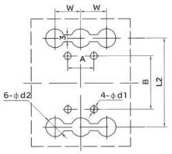
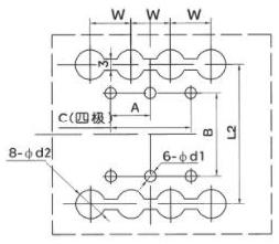
3 Poles 4 Poles
RDM5 series rear panel wiring appearance and installation dimensions
RDM5- 125M/H 160、250 RDM5-400、630、800
RDM5-125~800 rear wiring appearance and mounting plate opening size
| Product model | Size code | |||||||||
| H3 | H4 | D | W | L2 | d2 | A | B | C | d1 | |
| RDM5-125M H | 64 | 100 | M8 | 50 | 132 | 24 | 30 | 108 | 60 | 5.5 |
| RDM5-160L.M | ||||||||||
| RDM5-250L、M、H | 70 | 100 | M10 | 35 | 145 | 15 | 35 | 126 | 70 | 5.5 |
| RDM5-400L.M、H RDM5-630S |
71 | 105.5 | - | 48 | 2242 | 32 | 44 | 194 | 94 | 7 |
| RDM5-630L.M、H | 46 | 105 | - | 58 | 2346 | 37 | 58 | 200 | 116 | 7 |
| RDM5-800L,M.H | 105 | 105 | - | 70 | 2436 | 48 | 70 | 243 | 70 | 7.5 |
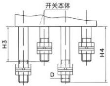
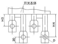
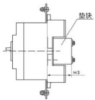
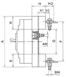
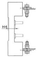
RDM5 series plug-in front panel dimensions
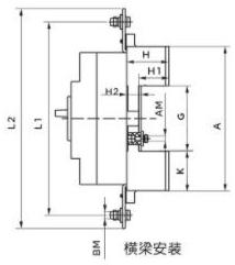
Flat mount
Dimensions of RDM5-125~800 plug-in front panel circuit breaker
| Product model | Size code | |||||||||||||
| A | G | K | H | H | ₂ | Hs | L1 | L2 | AM | BM | ||||
| RDM5-125M H | 172 | 95 | 38.5 | 50.5 | 35 | 16.5 | 61 | 185 | 217 | M6 | M8 | |||
| RDM5-160L,M | ||||||||||||||
| RDM5-250L,M、H | 183 | 95 | 44 | 52 | 35 | 18 | 65 | 230 | 259 | M6 | M10 | |||
| RDM5-400L,M,H RDM5-630S |
276 | 170 | 53 | 79.5 | 67 | 18 | - | 322 | 352 | M6 | M10 | |||
| RDM5-630L,M、H | 299 | 163.5 | 67.5 | 84.5 | 65.5 | 20 | - | 368 | 397 | M8 | M12 | |||
| RDM5-80OL,M,H | 303 | 179 | 62 | 87.5 | 60.5 | 28 | 118 | 375 | 405 | M10 | M12 | |||
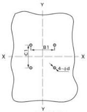
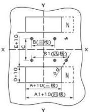
Hole size of the plug-in front wiring mounting plate (X-XY-Y is the center of the circuit breaker)
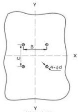
Beam installation Flat mount
RDM5-125~800 plug-in front wiring mounting plate opening size
| Product model | RDM5-125M.H RDM5-160L.M |
RDM5-250L.M,H | RDM5-400L,M,H RDM5-630S |
RDM5-630L,M,H | RDM5-800L,M.H | |||||||||
| pole | 3 | 3 | 3 | 3 | 3 | |||||||||
| Mounting plate opening size(mm) | B | 66 | 70 | 115 | 90.5 | 90.5 | ||||||||
| B1 | 50 | 60 | - | - | 65 | |||||||||
| C | 60 | 64 | 135 | 144.5 | 144.5 | |||||||||
| C1 | 35 | 35 | - | - | 80 | |||||||||
| d | 6.5 | 6.5 | 6.5 | 8.5 | 11 | |||||||||
RDM5 series plug-in panel rear dimensions and mounting panel opening dimensions
Dimensions of RDM5-125~800 plug-in rear panel circuit breaker
| Product model | Size code | ||||||||||
| A | F | G | K | H | H1 | H2 | H3 | H4 | AM | BM | |
| RDM5-125M H RDM5-160L M |
168 | 133 | 92 | 38 | 48 | 32.5 | 32.5 | 18 | 17 | M6 | M8 |
| RDM5-25OL、M、H | 186 | 144 | 95 | 45.5 | 49.5 | 33.5 | 34 | 15 | 17 | M6 | M8 |
| RDM5-400L、M、H RDM5-630S |
280 | 224 | 171 | 54.5 | 59.5 | 40 | 44 | 23.5 | 20 | M8 | M12 |
| RDM5-630L、M、H | 300 | 234 | 170 | 65 | 59 | 40 | 50 | 30 | 20 | M8 | M12 |
| RDM5-800L、M、H | 305 | 243 | 181 | 62 | 87 | 60 | - | - | 28 | M10 | M14 |
Hole size of plug-in rear wiring installation panel (X-XY-Y is the center of the circuit breaker)
RDM5-125~800 plug-in rear wiring installation panel opening size
| Product model | RDM5-125M.H RDMS-160L.M |
RDM5-25OL,M,H | RDM5-400L、M、H RDM5-630S |
RDM5-630L M.H | RDM5-80OL. M.H | |||||||
| pole | 3 | 4 | 3 | 4 | 3 | 4 | 3 | 4 | 3 | 4 | ||
| Mounting plate opening size(mm) | A | 91 | - | 107 | - | 149 | - | 182 | - | 210 | - | |
| A1 | - | 129 | - | 145 | - | 200 | - | 242 | - | 290 | ||
| B | 60 | - | 70 | - | 60 | - | 100 | - | 90 | - | ||
| B1 | - | 90 | - | 105 | - | 108 | - | 158 | - | 162 | ||
| C | 56 | 54 | 129 | 123 | 146 | |||||||
| D | 38 | 45.5 | 54.5 | 65 | 62 | |||||||
| E | 92 | 95 | 171 | 170 | 181 | |||||||
| d | 6.5 | 6.5 | 8.5 | 8.5 | 11 | |||||||