


1.Temperature: no higher than +40℃,and no lower than -5°C, and the average temperature no higher than +35°C
2.Installation location no more than 2000m
3.The relative humidity: no more than 50%, when Temperature is +40°C.The product can withstand the higher humidity under lower temperature, for instance, when temperature at +20℃,the product can withstand 90% relative humidity.The condensation that happened because of temperature changes should be taken care with special measurements
4.Class of pollution:3 Class
5.It should be installed at the place that have no danger of explosion, it also has no gas and conductive dust which would cause metal-corrosion and insulation-damage
6.Maximum install inclined Angle 5°, it should be installed at the place has no obvious impact and weather-influence
7.Main circuit installation type: Ⅲ, Auxiliary circuit and control circuit installation type: ll
8.External magnetic field of installation location should not exceed than 5 times of earth magnetic field
9.Installation electromagnetic environment:B type
1.Pole:2P, 3P and 4P(2P product onlyhas RDML-125L/2300,RDM1L-125M/2300,RDM1L-250M/2300,RDM1-250M/2300)
2.Connection type: front board connection, back board connection and plug-in type
3.Application: power-distribution type and motor-protection type
4.Residual current release type: electromagnetic type, instantaneous type
5.Residual current breaking time: delay type and Non-delay type
6.Rated limited short-circuit breaking capacity: L-standard type, M-Medium type, H-high type
7.Operational type: Handle-directed operation, Motor operation(P), rotation-handle operation(Z,for cabinet)
1.Ui=6goV, Uimp=8kV, the main technical parameter see Table1.
| Model No.(Table 1) | Rated current ln (A) | Rated operational voltage (V) | Rated short-circuit breaking capacity R | Rated residual short circuit making and breaking capacity lm (A) | Rated residual action current In(mA) | Arc distance mm | |
| lcu (kA) | lc (skA) | ||||||
| RDM1L-125L | 10、16、20、25、32、40、50、63、80、100、125 | 400 | 35 | 22 | 25%lcu | 30/100/300 No delay type | ≤50 |
| RDM1L-125M | 50 | 35 | |||||
| RDM1L-125H | 85 | 50 | |||||
| RDM1L-250L | 100、125、160、180、200、225、250 | 400 | 35 | 22 | 25%lcu | 100/300/500 | ≤50 |
| RDM1L-250M | 50 | 35 | |||||
| RDM1L-250H | 85 | 50 | |||||
| RDM1L-400L | 225、250、315、350、400 | 400 | 50 | 25 | 25%lcu | 100/300/500 | ≤100 |
| RDM1L-400M | 65 | 35 | |||||
| RDM1L-400H | 100 | 50 | |||||
| RDM1L-800L | 400、500、630、700、800 | 400 | 50 | 25 | 25%lcu | 300/500/1000 | ≤100 |
| RDM1L-800M | 70 | 35 | |||||
| RDM1L-800H | 100 | 50 | |||||
| Code(Table 2) | Instruction |
| A type | N pole has no overload release, and N pole is always connected and do not connect or break with the other 3 pole together. |
| B type | N pole has no overload release, and N pole connect or break with the other 3 pole together. |
| C type | N pole has overload release, and N pole connect or break with the other 3 pole together. |
| D type | N pole has overload release, and N pole always connected,do not connected or break with the other 3 pole together. |
2.Circuit breaker residual current action protection time see Table3
| Residual current(Table 3) | l△n | 2l△n | 5l△n | 10l △n | |
| Non-delay type | Max breaking time (s) | 0.3 | 0.15 | 0.04 | 0.04 |
| Delay type | Max breaking time (s) | 0.4/1.0 | 0.3/1.0 | 0.2/0.9 | 0.2/0.9 |
| Limited undrive time t (s) | - | 0.2/0.5 | - | - | |
3.Overload release consists of the thermal long-delay release which has inverse-time characteristic and instantanous action release, the action feature see Table4
| Power-Distribution circuit breaker(Table 4) | Motor-protection circuit breaker | ||||||
| Rated current ln(A) | Thermal release | electromagneticrelease action current | Rated current ln (A) | Thermal release | electromagnetic release action current | ||
| 1.05ln(cool state) Non-action time(h) |
1.30ln(heat state) Action time(h) |
1.0 ln(cool state) non-action time (h) | 1.20ln (heat state) action time (h) | ||||
| 10≤ ln ≤63 | 1 | 1 | 10ln±20% | 10≤ln≤800 | 2 | 2 | 12ln±20% |
| 63<ln ≤l25 | 2 | 2 | |||||
| 125<ln ≤800 | 2 | 2 | 5ln±20% 10ln±20% | ||||
Accessory device technical parameter
1.Rated value of auxiliary contact and alarming contact, see Table 5
| Contact(Table 5) | Frame size rated current | conventional heating current lth (A) | Rated operation current le (A) | |
| AC400V | DC220V | |||
| Auxiliary contact | lnm≤400 | 3 | 0.3 | 0.15 |
| lnm≥400 | 3 | 0.4 | 0.15 | |
| Alarm contact | 100≤lnm≤800 | 3 | 0.3 | 0.15 |
2.Control circuit release and motor rated control power voltage (Us) and rated operational voltage (Ue) See Table6
| Type | Rated voltage (V) | |||
| AC 50Hz | DC | |||
| Release | shunt release | Us | 230 400 | 110 220 |
| undervoltage release | Ue | 230 400 | - | |
| motor mechanism | Us | 230 400 | 110 220 | |
①Shunt release external voltage is between rated control power voltage 70%~110%, it can tripping the release reliably.
②When power supply voltage decrease to 70% to 35% under-voltage rated operating voltage, under-voltage release can breaking the line. When the power supply voltage is higher than 85% of under-voltage release rated operating voltage, the under-voltage release will that circuit breaker close.
Warning: Under-voltage release must be charged at first, then circuit breaker closed. If not, the circuit breaker would be damaged.
③Motor operation mechanism ensure that it can make the circuit breaker closed when the power voltage is between 85% -110%, under rated frequency.
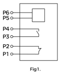
3.Leakage alarming module (RDM1 L-125L, 250L do not have it.) Specification: P5-P6 port for input power-source AC50/60Hz, 230V or 400V. P1 -P2, P3-P4 port for capacity is AC230V 5A, see Fig1
Note: ①Mode ll could satisfy the speacial place needs, User adopts this function after the consideration
②Circuit breaker with leakage alarming module. when the leakage alarming is happening, the leakage protection module would function after reseting the reset button of Module ll.Fig1.

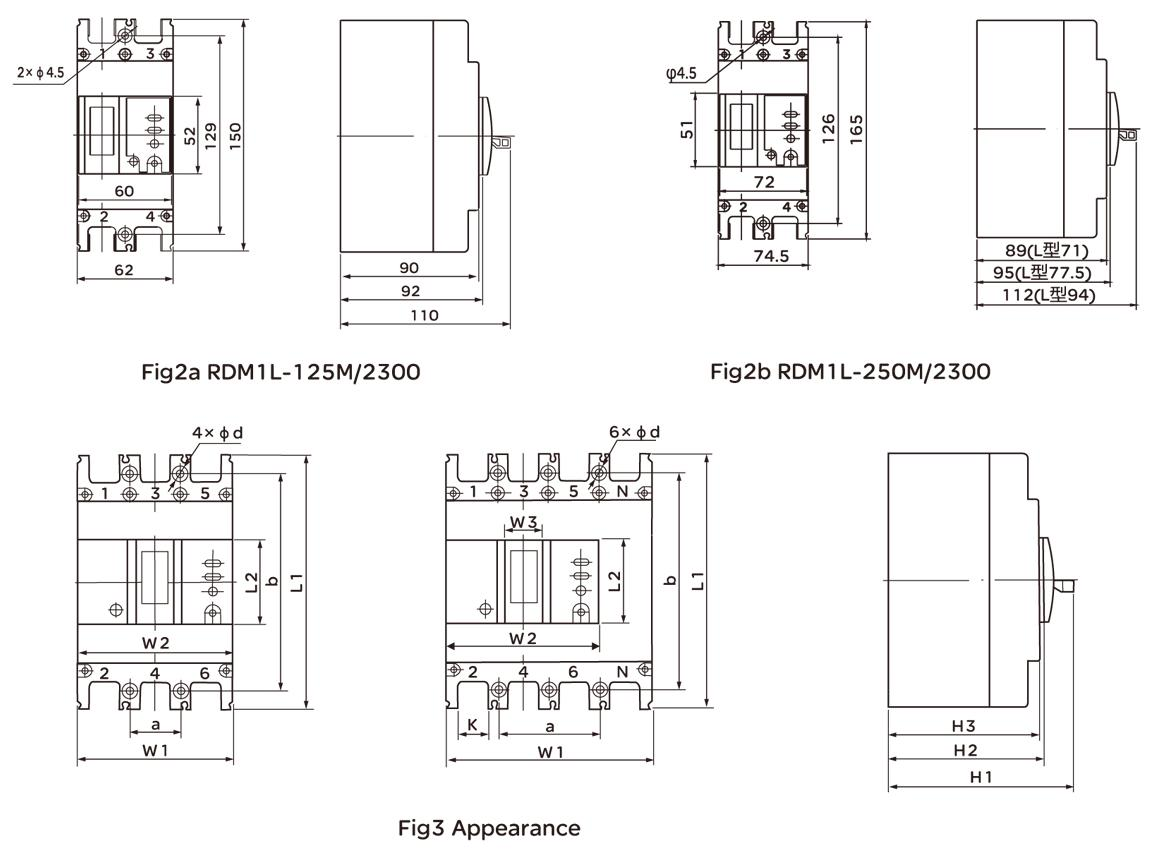
Appeatance and Installation dimension see Fig2, Fig3 and Fig8.

| Model No. | Pole | Front board connection | Installation Dimension | ||||||||||
| L1 | L2 | W1 | W2 | W3 | H1 | H2 | H3 | K | a | b | φd | ||
| RDM1L-125L | 3 | 150 | 52 | 92 | 88 | 23 | 94 | 75 | 72 | 18 | 30 | 129 | φ4.5 |
| 4 | 150 | 52 | 122 | 88 | 23 | 94 | 75 | 72 | 18 | 60 | 129 | φ4.5 | |
| RDM1L-250L | 4 | 150 | 52 | 92 | 88 | 23 | 110 | 92 | 90 | 18 | 30 | 129 | φ4.5 |
| 3 | 150 | 52 | 122 | 88 | 23 | 110 | 92 | 90 | 18 | 60 | 129 | φ4.5 | |
| RDM1L-250M.H | 3 | 165 | 52 | 107 | 102 | 23 | 94 | 72 | 70 | 23 | 35 | 126 | φ5 |
| 3 | 165 | 62 | 142 | 102 | 23 | 94 | 72 | 70 | 23 | 70 | 126 | φ5 | |
| RDM1L-400 | 3 | 165 | 52 | 107 | 102 | 23 | 110 | 90 | 88 | 23 | 35 | 126 | φ5 |
| 4 | 165 | 62 | 142 | 102 | 23 | 110 | 90 | 88 | 23 | 70 | 126 | φ5 | |
| RDM1L-800 | 4 | 257 | 130 | 150 | 150 | 65 | 150 | 110 | 108 | 32 | 44 | 194 | φ7 |
| 4 | 257 | 92 | 198 | 142 | 65 | 150 | 110 | 108 | 32 | 44 | 194 | φ7 | |
Main technical parameter
4.1 Ui=690V, Uimp=8kV, the main technical parameter see Table3.
| Model No. | Rated current ln (A) | Rated operational voltage (V) | Rated short-circuit breaking capacity R | Rated residual short circuit making and breaking capacity lm (A) | Rated residual action current In(mA) | Arc distance mm | |
| lcu (kA) | lc (skA) | ||||||
| RDM1L-125L | 10 16 20 25 32 40 50 63 80 100 |
400 | 35 | 22 | 25%lcu | 30/100/300 No delay type 100/300/500 delay type |
≤50 |
| RDM1L-125M | 50 | 35 | |||||
| RDM1L-125H | 85 | 50 | |||||
| RDM1L-250L | 100、125、160、180、200、225 | 400 | 35 | 22 | 25%lcu | 100/300/500 | ≤50 |
| RDM1L-250M | 50 | 35 | |||||
| RDM1L-250H | 85 | 50 | |||||
| RDM1L-400L | 225、250、315、350、400 | 400 | 50 | 25 | 25%lcu | 100/300/500 | ≤50 |
| RDM1L-400M | 65 | 35 | |||||
| RDM1L-400H | 100 | 50 | |||||
| RDM1L-800L | 400、500、630、700、800 | 400 | 50 | 25 | 25%lcu | 300/500/1000 | ≤50 |
| RDM1L-800M | 70 | 35 | |||||
| RDM1L-800H | 100 | 50 | |||||
4.2 Circuit breaker residual current action protection time see Table4
| Residual current | l△n | 2I△n | 5I△n | 10I △n | |
| Non-delay type | Max breaking time (s) | 0.3 | 0.15 | 0.04 | 0.04 |
| Delay type | Max breaking time (s) | 0.4/1.0 | 0.3/1.0 | 0.2/0.9 | 0.2/0.9 |
| Limited undrive time t (s) | - | 0.1/0.5 | - | - | |
4.3 Overload release consists of the thermal long-delay release which has inverse-time characteristic and instantanous action release, the action feature see Table5
| Power-Distribution circuit breaker | Motor-protection circuit breaker | ||||||
| Rated current ln (A) | Thermal release | Rated current ln (A) | Thermal release | electromagnetic release action current | |||
| 1.05ln (cool state) Non-action time (h) |
1.30ln (heat state) Action time (h) |
electromagneticrelease action current | 1.0 ln (cool state) non-action time (h) | 1.20ln (heat state) action time (h) |
|||
| 10≤ln≤63 | 1 | 1 | 10ln±20% | 10≤ln≤630 | 2 | 2 | 12ln±20% |
| 63<ln≤l00 | 2 | 2 | |||||
| 100<ln≤800 | 2 | 2 | 5ln±20% 10ln±20% | ||||
4.4 Accessory device technical parameter
4.4.1 Auxiliary contact and alarm contact rated value, see Table 6
| Contact | Frame size rated current | conventional heating current lth (A) | Rated operation current le (A) | |
| AC400V | DC220V | |||
| Auxiliary contact | lnm≤225 | 3 | 0.3 | 0.15 |
| lnm≥400 | 3 | 0.4 | 0.15 | |
| Alarm contact | 100≤lnm≤630 | 3 | 0.3 | 0.15 |
4.4.2 Control circuit release and motor rated control power voltage (Us) and rated operational voltage (Ue) See Table7.
| Type | Rated voltage (V) | |||
| AC 50Hz | DC | |||
| Release | shunt release | Us | 230 400 | 24 110 220 |
| undervoltage release | Ue | 230 400 | ||
| motor mechanism | Us | 230 400 | 110 220 | |
4.4.2.1 Shunt release external voltage is between rated control power voltage 70%~110%, it can tripping the release reliably.
4.4.2.2 When power supply voltage decrease to 70% to 35% under-voltage rated operating voltage, under-voltage release can breaking the line. When the power supply voltage is higher than 85% of under-voltage release rated operating voltage, the under-voltage release will that circuit breaker close. Warning: Under-voltage release must be charged at first, then circuit breaker closed. If not, the circuit breaker would be damaged.
4.4.2.3 Motor operation mechanism ensure that it can make the circuit breaker closed when the power voltage is between 85% -110%, under rated frequency.
4.4.3 Leakage alarming module (RDM1 L-125L, 250L do not have it.) Specification: P5-P6 port for input power-source AC50/60Hz, 230Vor 400V. P1 -P2, P3-P4 port for capacity is AC230V 5A, see Fig1
Note:
1. Mode II can meet special site requirements, users adopt this function after the consideration.
2. Circuit breaker with leakage alarming module, when the leakage alarming is happening, the leakage protection module would function after resetting the reset button of Module II.Fig1.
5.1 Appearance and Installation dimension see Fig2, Fig3 and Fig8.
| Model No. | Pole | Front board connection | Installation Dimension | ||||||||||
| L1 | L2 | W1 | W2 | W3 | H1 | H2 | H3 | K | a | b | Φ d | ||
| RDM1L-125L | 3 | 150 | 52 | 92 | 88 | 23 | 94 | 75 | 72 | 18 | 30 | 129 | Φ 4.5 |
| 4 | 150 | 52 | 122 | 88 | 23 | 94 | 75 | 72 | 18 | 60 | 129 | Φ 4.5 | |
| RDM1L-250L | 4 | 150 | 52 | 92 | 88 | 23 | 110 | 92 | 90 | 18 | 30 | 129 | Φ 4.5 |
| 3 | 150 | 52 | 122 | 88 | 23 | 110 | 92 | 90 | 18 | 60 | 129 | Φ 4.5 | |
| RDM1L-250M.H | 3 | 165 | 52 | 107 | 102 | 23 | 94 | 72 | 70 | 23 | 35 | 126 | Φ 5 |
| 3 | 165 | 62 | 142 | 102 | 23 | 94 | 72 | 70 | 23 | 70 | 126 | Φ 5 | |
| RDM1L-400 | 3 | 165 | 52 | 107 | 102 | 23 | 110 | 90 | 88 | 23 | 35 | 126 | Φ 5 |
| 4 | 165 | 62 | 142 | 102 | 23 | 110 | 90 | 88 | 23 | 70 | 126 | Φ 5 | |
| RDM1L-800 | 4 | 257 | 130 | 150 | 150 | 65 | 150 | 110 | 108 | 32 | 44 | 194 | Φ 7 |
| 4 | 257 | 92 | 198 | 142 | 65 | 150 | 110 | 108 | 32 | 44 | 194 | Φ 7 | |
| RDM1L-100M.H | 4 | 280 | 138 | 210 | 210 | 66 | 150 | 116 | 111 | 44 | 70 | 243 | Φ 7 |
| 3 | 280 | 92 | 280 | 182 | 67 | 150 | 116 | 111 | 44 | 70 | 243 | Φ 7 | |